
Page 37 - Human Environment Interface (3)
P. 37
Learning Intermittent Strategy
where I, h, and T represent the moment of inertia around the manifolds of dx=dt~Ax in the h-v plane are given, respectively,
joint, the tilt angle from the upright position, and the total torque by the straight lines passing through the origin;
acting at the joint, respectively. m, g, and h are the mass, the
gravitational acceleration, and the length between the joint and v~l{h*{1:53h ð4Þ
the center of mass of the pendulum, respectively. The term mghh
approximates the gravitational toppling torque for small h. Values and v~lzh*1:28h ð5Þ
of these parameters were similar to those of a typical human body, where
and fixed as in Table 1.
l+ ~ 1 qffiffiffiffiffiffiffiffiffiffiffiffiffiffiffiffiffiffiffiffiffiffiffiffiffiffiffiffiffiffiffiffiffiffiffiffiffiffiffiffiffiffiffiffiffiffi ð6Þ
The total torque T was modeled as T~TpzTa, where Tp was {B=I + ðB=IÞ2z4(mgh{K)=I :
the passive torque determined by a torsional viscoelastic element 2
at the joint, and Ta the active torque determined by the muscle
activations derived from subjects. The passive torque was Thus, time constants of the stable and the unstable dynamic modes
implemented as Tp~{Kh{Bh_ , where K and B are the passive are 0.65 s and 0.78 s, respectively. Solutions (trajectories) gener-
elastic and viscous coefficients. The active torque was determined ated by the vector field of dx=dt~Ax in the h-v plane exhibit
by the difference between the antagonist torques as hyperbolic curves that approach the saddle point at x~0 along the
Ta~TTA{TMG, where TTAw0 and TMGw0 represent, respec- stable manifold and fall away from the saddle point along the
tively, the forward and the backward bending torques. TTA and unstable manifold.
TMG were determined based on the iEMG signals derived from
TA and MG muscles of subjects, respectively (see below). If this mechanical body plant is actively actuated by a
continuous delay feedback control that approximates the neural
The state space representation of Eq. 1 is as follows. feedback control with a neural transmission delay, a non-negligible
risk of the delay-induced instability arises. For example, if we
d h 0 1 ! h 0 assume a simple proportional and derivative (PD) control with no
~ mgh{K 1 delay, the unstable saddle point can easily be stabilized asymp-
Bz ð2Þ totically for a proportional gain greater than 0.2 mgh with any
dt v I { v I TTA{TMG positive derivative (velocity) gain. However, if a typical neural
I transmission delay of 0.2 s is introduced for the PD feedback
control, the upright equilibrium can be destabilized by a Hopf
where v~dh=dt. We also use the following abstract formulation bifurcation [14,56]. Indeed, for small values of derivative gain, the
of Eq. 2. proportional gain of 0.2 mgh is a critical value, meaning that the
proportional gain greater than 0:2 mgh destabilizes the upright
dx ð3Þ equilibrium. See [44] for safety parameter regions of the gains in
dt ~Axzu the delay feedback control, and confirm that the feedback gains
(thus the joint impedance) must be carefully tuned for the
where x~(h,v)T , and u is the active control torque vector. The stabilization, if the continuous feedback control is employed. A
term Ax defines the vector field of the non-actively-actuated reaction time to visually supplied falling motions of the virtual
pendulum with u~0. inverted pendulum in this study corresponds to the feedback time
delay, and in the later section, we show that it was much larger
According to experimental evaluations of the passive ankle than 0.2 s, implying that stabilization of the upright equilibrium by
visco-elasticity during human quiet standing [54,55], we set as the use of continuous feedback control is not easy.
K~0:8mgh Nm/rad and B~15 Nms/rad. (The value of B used
here might be several times larger than human passive viscosity.
However, it was too difficult for most of the subjects to stabilize the
pendulum for a smaller value of B.) Thus, mgh{Kw0, and the
upright state x~(0,0)T is an unstable equilibrium of saddle type,
with stable and unstable manifolds when Ta~0 (u~0) [32]. For
the pendulum parameter values used here, the stable and unstable
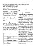
Table 1. Parameter values of the virtual inverted pendulum. 2.4 Setup of the EMG-based human-computer interface
Symbol Description Value with Unit EMG signals were monitored from TA and MG muscles of both
m 60 kg legs using bipolar surface electrodes separated by 1 cm and a
g Mass of the pendulum 9.8 m/s2 biosignal amplifier (BA1104, TEAC, Inc., Tokyo). Body sway of
h 1.0 m subjects was recorded as the vertical ground reaction force (Fz), the
Gravitational constant moment around the mediolateral axis (Mx) and the moment
I 60 kgm2 around the anterior-posterior axis (My) using a force platform
length between joint (Advanced Mechanical Technology, Inc., USA). Mx=Fz repre-
K and CoM 0.8 mghNm/rad sented motions of Center of Pressure of subjects in the anterior-
posterior direction, referred to as CoPAP. The EMG signals only
B Moment of inertia of 15 Nms/rad from the right leg were fed into the DSP (DSK6713IF-A,
the pendulum Hiratsuka Engineering Co. Ltd., Japan) with a sampling frequency
of 1 kHz through a 16 bit A/D converter mounted on the DSP,
Passive elastic coefficient of and numerically rectified in the DSP and then processed by the
the joint second order Butterworth filter with a cutoff frequency of 12 Hz,
yielding the iEMG signals in real-time. The EMG signal from the
Passive viscosity coefficient left leg was not used for the active control of the pendulum, about
of the joint which subjects were not informed.
doi:10.1371/journal.pone.0062956.t001
PLOS ONE | www.plosone.org 4 May 2013 | Volume 8 | Issue 5 | e62956