
Page 489 - The City and Guilds Textbook: Plumbing Book 1 for the Level 3 Apprenticeship (9189), Level 2 Technical Certificate (8202) and Level 2 Diploma (6035)
P. 489
Chapter 7 Central heating systems
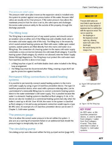
The pressure relief valve
The pressure relief valve (also known as the expansion valve) is installed onto INDUSTRY TIP
the system to protect against over-pressurisation of the water. Pressure relief
valves are usually set to 3 bar pressure. If the water pressure rises above the Pressure relief valves are
maximum pressure that the valve is set to, the valve opens and discharges most likely to open because of
the excess water pressure safely to the outside of the property through the lack of room in the system for
discharge pipework. expansion due to a malfunction
with the expansion vessel. This
The filling loop can be caused by:
The filling loop is an essential part of any sealed system, and should contain l the diaphragm in
an isolation valve at either end of the filling loop and a double check valve on the expansion vessel
the mains cold water supply side of the loop. The filling loop is the means by rupturing, allowing
water both sides of the
which sealed central heating systems are filled with water. Unlike open vented diaphragm
systems, sealed systems are filled directly from the mains cold water via a l the vessel having lost its
filling loop. The connection of a heating system to the mains cold water supply charge of air.
constitutes a cross-connection between the cold main (fluid category 1) and the
heating system (fluid category 3), which is not allowed under the Water Supply
(Water Fittings) Regulations. The filling loop must protect the cold water main
from backflow and this is done in two ways:
1 a filling loop has a type EC verifiable double check valve included in the filling
loop arrangement
2 the filling loop must be disconnected after filling, creating a type AUK3 air
gap for protection against backflow.
Permanent filling connections to sealed heating
systems
It is possible to permanently connect sealed heating systems to the mains p Figure 7.49 A pressure relief
cold water supply by using a type CA backflow prevention device. The type CA valve
backflow prevention device, when used with a pressure reducing valve, can be
used instead of a removable filling loop to connect a domestic heating system
direct to the water undertaker’s cold water supply. This is possible because the
water in a domestic heating system is classified as fluid category 3 risk. A CA
device can also be installed on a commercial heating system but only when the
boiler is rated up to 45 kW. Over 45 kW, the water in the system is classified
as fluid category 4 risk and so any permanent connection would require a type p Figure 7.50 The filling loop
BA RPZ valve. An example of a CA backflow prevention device can be seen in
Chapter 5, Cold water systems. KEY POINT
An RPZ valve, or BA
The pressure gauge backflow prevention
device, is used to protect
This is to allow the correct water pressure to be set within the system. It fluid category 1 water
also acts as a warning of component failure or an undetected leak should the from fluid category
pressure begin to inexplicably rise or fall. 4 water. They were
described in detail in
The circulating pump Chapter 5, Cold water
systems.
Circulating pumps were discussed within the fully pumped section (page 447).
477
9781510416482.indb 477 29/03/19 9:03 PM