
Page 490 - The City and Guilds Textbook: Plumbing Book 1 for the Level 3 Apprenticeship (9189), Level 2 Technical Certificate (8202) and Level 2 Diploma (6035)
P. 490
The City & Guilds Textbook: Plumbing Book 1
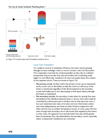
Pressure gauge
60
40 80
20 100
0
Type CA
device
Pressure relief valve
and discharge pipework Expansion vessel Cold water supply
p Figure 7.51 A sealed system with CA backflow prevention device
Low loss headers
For a boiler to work at its maximum efficiency, the water velocity passing
through the heat exchanger needs to remain constant, with little fluctuation.
This is especially important for condensing boilers as they rely on a defined
temperature drop across the flow and return before the condensing mode
begins to work effectively. Installation of a low loss header allows the creation
of two separate circuits. These are shown in Figure 7.52.
1 The primary circuit: the flow within the primary circuit can be maintained
at the correct rate for the boilers so that the maximum efficiency of the
boilers is maintained regardless of the demand placed on the secondary
circuit. Each boiler has its own shunt pump so that equal velocity through
the boilers is maintained.
2 The secondary circuits: the secondary circuits allow for varying flow rates
demanded by the individual balanced zones or circuits. Each zone would be
controlled by a shunt pump set to the flow rate for that particular zone. A
two-port motorised zone valve, time clock and room thermostat control
each zone independently, and these are often fitted in conjunction with
other controls such as outdoor temperature sensors. In some cases, the flow
rates through each secondary circuit will exceed that required by the boilers.
In other cases, the opposite is true and the boiler flow rate will be greater
than the maximum flow rate demanded by the secondary circuits, especially
where multiple boiler installations are concerned.
478
9781510416482.indb 478 29/03/19 9:03 PM