
Page 500 - The City and Guilds Textbook: Plumbing Book 1 for the Level 3 Apprenticeship (9189), Level 2 Technical Certificate (8202) and Level 2 Diploma (6035)
P. 500
The City & Guilds Textbook: Plumbing Book 1
The system remembers key points, such as how quickly the building heats up
or cools down, and makes its own adjustments so that energy savings can be
made. If it is very cold outside at, say, 2 am, the BMS will switch the heating on
at 4.15 am to allow the building to be at the correct temperature by the time
the user has set the heating to come on – say, 7 am – irrespective of the time
that the user has set for the heating to activate. On milder nights, the heating
may not come on until 6.15 am but it will still reach its set point by 7 am.
It will also learn how well your house retains heat and may shut down early if
it calculates that your set point will still be maintained at your ‘off’ time of, say,
10 pm.
These systems provide a cost-effective means of monitoring system efficiency
and can reduce heating costs by up to 30 per cent.
Electronic sensors are fitted to the flow and return pipework, and an external
temperature sensor is fitted for weather compensation. The information is
used to accurately vary the system output according to demand. This helps
to significantly reduce fuel wastage caused by temperature overshoot, heat
saturation of the heat exchanger, unnecessary boiler cycling and flue gas losses,
while maintaining internal comfort levels and reducing CO emissions.
2
System design and control
Now that we have seen the controls and the system layouts, we must look at
how the controls work together to ensure efficient operation of the systems.
We will concentrate on fully pumped systems as these are the systems that we
must install on new installations.
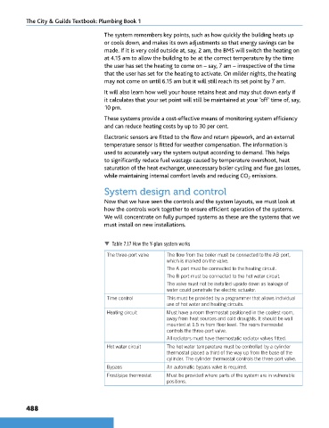
Table 7.17 How the Y-plan system works
The three-port valve The flow from the boiler must be connected to the AB port,
which is marked on the valve.
The A port must be connected to the heating circuit.
The B port must be connected to the hot water circuit.
The valve must not be installed upside down as leakage of
water could penetrate the electric actuator.
Time control This must be provided by a programmer that allows individual
use of hot water and heating circuits.
Heating circuit Must have a room thermostat positioned in the coolest room,
away from heat sources and cold draughts. It should be wall
mounted at 1.5 m from floor level. The room thermostat
controls the three-port valve.
All radiators must have thermostatic radiator valves fitted.
Hot water circuit The hot water temperature must be controlled by a cylinder
thermostat placed a third of the way up from the base of the
cylinder. The cylinder thermostat controls the three-port valve.
Bypass An automatic bypass valve is required.
Frost/pipe thermostat Must be provided where parts of the system are in vulnerable
positions.
488
9781510416482.indb 488 29/03/19 9:03 PM