
Page 123 - APPLIED PROCESS DESIGN FOR CHEMICAL AND PETROCHEMICAL PLANTS, Volume 1, 3rd Edition
P. 123
Fluid Flow 107
Table 2-12B
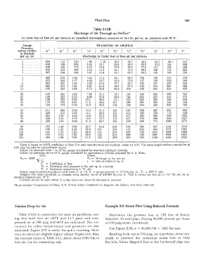
Discharge of Air Through an Orifice*
In cubic feet of free air per minute at standard atmospheric pressure of 14.7 lb. per sq. in. ahsolute and 70° F.
Gauge DIAMETER OF ORIFICE
Pressure
.i:«
before Orifice .v.>. n" %" %:" %" Y2" %" %'" Ys" 1.
1,,
64
32
in Pounds ---- I I I I I I I I
per sq. in. Discharge in Cubic feet of free air per minute
-,
1. ........... .028 .112 .450 1.80 7.18 16.2 28.7 45.0 64.7 88.1 115
2 ............ .040 .158 .633 2.53 10.1 22.8 40.5 63.3 91.2 124 162
3 ............ .048 .194 .775 3.10 12.4 27.8 49.5 77.5 111 152 198
4 .......•.... .056 .223 .892 3.56 14.3 32.1 57.0 89.2 128 175 228
5 ............ .062 .248 .993 3.97 15.9 35.7 63.5 99.3 143 195 254
- -··
6 .068 .272 1.09 4.34 17.4 39.1 69.5 109 156 213 278
7 .073 .293 1.17 4.68 18.7 42.2 75.0 117 168 230 300
g .083 .331 1.32 5.30 21.2 47.7 84.7 132 191 260 339
12 .095 .379 1.52 6.07 24.3 54.6 97.0 152 218 297 388
15 .105 .420 1.68 6.72 26.9 60.5 108 168 242 329 430
- - ----
20 .123 .491 1.96 7.86 31.4 70.7 126 196 283 385 503
25 .140 .562 2.25 8.98 35.9 80.9 144 225 323 440 575
30 .158 .633 2.53 10.1 40.5 91.1 162 253 365 496 648
35 .176 .703 2.81 11.3 45.0 101 180 281 405 551 720
40 .194 .774 3.10 12.4 49.6 112 198 310 446 607 793
-
45 .211 .845 3.38 13.5 54.1 122 216 338 487 662 865
50 .229 .916 3.66 14.7 58.6 132 235 366 528 718 938
60 .264 1.06 4.23 16.9 67.6 152 271 423 609 828 1082
70 .300 1.20 4.79 19.2 76.7 173 307 479 690 939 1227
80 .335 1.34 5.36 21.4 85.7 193 343 536 771 1050 1371
- -
90 .370 1.48 5.92 23.7 94.8 213 379 592 853 1161 1516
100 .406 1.62 6.49 26.0 104 234 415 649 934 1272 1661
110 .441 1.76 7.05 28.2 113 254 452 705 1016 1383 1806
120 .476 1.91 7.62 30.5 122 274 488 762 1097 1494 1951
125 .494 1.98 7.90 31.6 126 284 506 790 1138 1549 2023
Table is based on 100% coefficient of flow. For well rounded entrance multiply values by 0.97. For sharp edged orifices a multiplier of
0.65 may be used for approximate results.
Values for pressures from 1 to 15 lbs. gauge calculated by standard adiabatic formula.
Values for pressures above 15 lb. gauge calculated by approximate formula proposed by S. A. Moss.
aCP1 Where:
W. = .5303 ,,. -- \V 8 = discharge in lbs. per sec.
1
V T 1 a = area of orifice in sq. in.
C = Coefficient of flow
P1 = Upstream total pressure in lbs. per sq. in. absolute
T 1 = Upstream temperature in °F. abs.
Values used in calculating above table were; C = 1.0, P 1 = gauge pressure + 14.7 lbs./sq. in. T1 = 530° F. abs.
Weights (W) were converted to volumes using density factor of 0.07494 lbs./cu. ft. This is correct for dry air at 14.7 lbs. per sq. in
absolute pressure and 70° F.
Formula cannot be used where P1 is less than two times the barometric pressure.
*By permission "Compressed Air Data," F. W. O'Neil, Editor, Compressed Air ,Hagazine, 5th Edition, New York, 1939 [49].
Friction Drop for Air Example 2-9: Stearn Flow Using Babcock Formula
Table 2-12A is convenient for most air problems, not- Determine the pressure loss in 138 feet of 8-inch
ing that both free air (60°F and 14.7 psia) and com- Schedule 40 steel pipe, flowing 86,000 pounds per hour
pressed air at 100 psig and 60°F are indicated. The cor- of 150 psig steam (saturated).
rections for other temperatui·es and pressures are also
indicated. Figure 2-37 is useful for quick checking. How- Use Figure 2-32, w = 86,000/60 = 1432 lbs/min
ever, its values are slightly higher (about 10 percent) than Reading from top at 150 psig, no superheat, down ver-
the rational values of Table 2-11, above about 1000 cfm of tically to intersect the horizontal steam flow of 1432
free air. Use for estimating only. lbs/min, follow diagonal line to the horizontal pipe size