
Page 125 - APPLIED PROCESS DESIGN FOR CHEMICAL AND PETROCHEMICAL PLANTS, Volume 1, 3rd Edition
P. 125
Fluid Flow 109
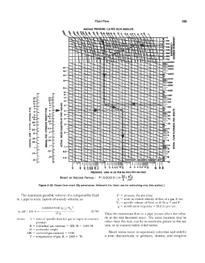
AVERAGE PRESSURE -LB. PER SQ. IN. ABSOLUTE
·'-" '�� �" \"\ ""� ,,, -& \\ t,\' Cl\�,\'\'\\ .. ,
' .x
� -� " � ....:i� � �I\ \ " ....... .\ '- '\ 0
,._� � r-� � L \ ' .... - \ ' - \ '·" ., \ IOO �
l
I
-14i
-f.,\ 0
- " 1-,.l \ ,-.... ,� - \ u I\ I\ so� ..L ., . ' � �- \ \ 1 !00!
�
l..l
·oo a::
..... \...
_,
l "to u, ..... 11 o-•., ,...
-"\, "l"""' \ 1 � .... L_1 � t-- u \ \ { \ = ·- �
\ 1 \ II � I = --,, 1 I \ \ = ICO II>
700
I \ \ \ ,-.......1.. ,\ ;, M.� --i 1 c
-r- t-- t-- t-- r- r- i---.. t-- ' r- t--
r--, i---.. -i-- - ...... -i--. ........... - ....... ..... i--. .... t-- .... t--
1()- ...... - ........... ,___ 40000
l!O- r- r--. t--.. r--. -i---.. -t-- r- t--
- -i--. -r-.. t--.. 1--... ,-..... ...... ....... -i- 't..... -t..... - _oooo
-
40 -,-..... -i- .._
- -i--.- t--.. !-.... t-... r--. t--.. t..... �
r--, ,-..... t--.. :-.... t-- 1--...� t..... - ...... 't..... -t-- iliilEIOOOO
t..... .=-8000
:,0 - -r- -t..... - :-.... t-- t-- - -i- -
t--
i-�
,-.....
t--
t--
20 -- -r-� ,-..... r- - t-- t-- - ...... .......... :-.... c::-4000
,-.....
-
,-.....
.......
t--
t--
�
t--
16- -t-- t-- -- ....... ..... t-- t-- ...... t-- t-- - 2000
14-.: r- r- ,-..... t--.. t-- <, t---.. t-- I--... =--1000
1..-_ r--... r-_ - i,... I ,-..... t--.. - ....... -.._ --i-- -t-- §= ___
.......
:-.... .... ---r-. ..
-
10- r--... - ,-..... - ....... �- - ,-..... � ....... -t---.. .... i--. t..... �-�o
t--
.. _
t-- t-- ,-..... .... �- -- .....
I
- -i---.. ..... t-- I-..._ :--..._ --·� :-,... t-- 1--. -IQO
..._
·- t--
-
6 - - ..... � - '""· !-.... t--
....... �
,- r- t-- -- -- t--� t-- -...__ -i- t--
:-...._
-
- r--... t-- t-- r- -...__ -""- i- ,___ -
�
4 r- -r- -i---.. ""- ,-...._ I-.... 1--... t.....
.......
- - - .......
.....
.....
.....
:, :--- -- -.... :--... - i--... .....""- i- -=-r.o
.......
- ...... -- -- t-- t-- - -i---.. �.
�
-1--...
.......
- -:-.... - ""- t-- ....... ""- 1--... ==:10
.......
z- ...... ....... ....... ...... ...... ....... ....... t--
- ....... :--... -- ,..._ ...... -i,...J I --- ....._ i--. -- E-4
-....
.......
1--...
.......
- - - -.... -� i-,......_ !-.... ....... --- -i- i- - r.
.......
.......
.......
-
.......
t--
1--.
i--...
-i--.. ....... _ -- i-,... :--... ...... ....... i- :-.... �=
I t-- i-,... ...... ...... r---.. ...... -.... ...... i--. i--.
-....
......
o.a- !'-.. - -- -- r- t-- - ..... _ t---.. -i- -i---.. - ..
......
.75 -- -- ....... _ t-- i--... ....... ..... - ..... i- -
r--...
0.6 - -.... r- :-.... ..... 1--... -1--... ""- r-:t
.5 r---.. :--... ...... ..... t-- 1--... COPYRIGHT-WALWORTH COIINH'l'-1157 !§ -
11111p1111 I 1111 Iii' 111111 '11 11� � 13111111111111111r1Tl1""1'"l 111
JI
..
0. 2! s • q'° � ci Of i
• q q
PRESSURE LOSS IN Le. PER SQ. INCH PER 100 FEET
Based on Babcock Formula: P = 0.000131 (I+ d ;!}
3 6)
Figure 2-32. Steam flow chart. (By permission, Walworth Co. Note: use for estimating only (this author).)
The maximum possible velocity of a compressible fluid P' = pressure, Psi abs (Psia)
in a pipe is sonic (speed of sound) velocity, as: �· = sonic or critical velocity of flow of a gas, ft/sec
V 1 = specific volume of fluid, cu ft/lb at T and P'
0.000001959f (q'h) 2Sg 2 g = acceleration of gravity= 32.2 ft/per/sec
or, �p I l 00 ft = (2- 78)
d''p Thus the maximum flow in a pipe occurs when the veloc-
ity at the exit becomes sonic. The sonic location may be
where k = ratio of specific heat for gas or vapor al constant
pressure other than the exit, can be at restrictive points in the sys-
R = individual gas constant = MR/M = 1544/M tem, or at control/ safety relief valves.
M = molecular weight
MR = universal gas constant = 1544 Shock waves travel at supersonic velocities and exhibit
T = temperature of gas, R, = ( 460 + °F) a near discontinuity in pressure, density, and tempera-