
Page 20 - APPLIED PROCESS DESIGN FOR CHEMICAL AND PETROCHEMICAL PLANTS, Volume 1, 3rd Edition
P. 20
Process Planning, Scheduling and Flowsheet Design 7
� - o m_ . _ o f_ i c_s_(_2_0 � p_ s i_a_ l _ ������ Fuel Gas (20 psial
Cnusti c Synthesis Gas (435 psia) 3:IH2:N2l
Vents I Nifrogen
From
Air Plant
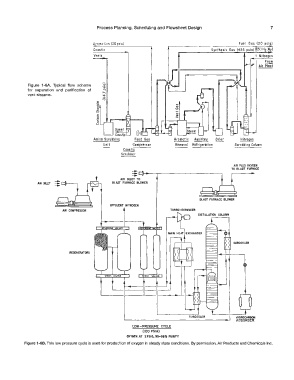
Figure 1-6A. Typical flow scheme
for separation and purification of
ver,t streams.
...
..,
·;:.
0
i:5
c
0
�
0
(.)
Feed Gas Aromatic Auxiliary Drier Nitrogen
Compressor Rem ova I Refrigeraf ion Scrubbing Column
Causfic
Scrubber
.... TO BLAST FVRNACE
AIR PLUS OXYGEN
.... L]���-.--�������������--,
-- TO
AIR INLET
AIR IHI.ET BLAST FURNACE BLOWER
BLAST FURNACE BLOWER
EFFLUENT N ITROOEN
AIR COMPRESSOR t TURBO-EXPANDER DISTILLATION COLUMN
SUBCOOLER
REGENERATORS
SUBCOOLER HYDffllCARIIOfl
AOSORBER
LOW-PRESSURE CYCLE
(100 PSIA)
OXYGEN AT 2 PSIG, 95-98 'rt PURLTY
Figure 1-68. This low pressure cycle is used for production of oxygen in steady state conditions. By permission, Air Products and Chemicals Inc.