Page 21 - APPLIED PROCESS DESIGN FOR CHEMICAL AND PETROCHEMICAL PLANTS, Volume 1, 3rd Edition
P. 21

8                         Applied Process Design for Chemical and Petrochemical  Plants


                    Saturated  steam,
                     100 p1i9.   ,                                    E·I                    C-2
                     12 lb./hr.   \                              Distillation  tower    Product condenser
                                                                          1
                     14,275  Btu./hr.                            2!.4"dia.x 38 -0•       and separator
                                                                                        1•-e• dia.x 10•-o•
                                                                                     r  - - -  - - -  Coolin9  water
                                                                                      I             280.000 Btu./hr.
                                                                                       170 F.       28 !I pm.
                                                                                                     180F.
                                                                                                  To vacuum equipment
                                                                                                   12 lb. of water vapor/hr.
                                                                                                   Trace of noncondens·
                                                                                                   ables.
                                                                                                   13,075  Btu./hr.
                                                    Fatty acid
                                                   I
                                                   I   280MW                                          rF. A.distillate
                                                   I   lllO lb.ofvapar/hr.                            I   0.85 Sp. 9r.
                                            c-1      58 lb.of liquid/hr.             '-Reflux         I   9501b./hr.
                                            Reboiler   527 F.                        (not required    I  134 9al./hr.
                                  ,301,400                                            for design      I  zero Btu./hr.
                                                                                      feed)
                                                                                                        180 F.
                                     Btu./ht
                 r  Crude fatty acid
                    feed                          rF.A.liquid                               Product pump
                  I   0.85 sp.9r.                   0.75 sp.9r.                                 J-4  -A.  .
                    1,000 lb./hr                 1   1,768 lb./hr.                             225  I"  pitch
                    141  9al./hr.                I                                             gpmJ   0.711p.9r.
                    zero Btu./hr.                      475 F.                                     /   501b./hr.
                                                                                                  I   0.14 gprn.
                         180 F.                                                           475 F.     22,600 Btu./hr.
                           Charge pump                                    Bottoms  pump
                              J-1                                            J-3
                            2.35 9prn.
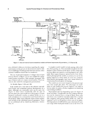
                    Figure  1-7.  Heat and material  balance establishes material and thermal  requirements.  By permission, J.P. O'Donnell [9].


             area,  definitely influences decisions regarding the equip-   A complete model  usually includes  piping,  valves,  lad-
             ment layout on the ground,  in the structures, and in rela-   ders, floor grating,  etc. This essentially completes the visu-
             tion to buildings.  Prevailing wind direction and any other   alization of  the condition of  the layout.  In fact,  many engi-
             unusual conditions should also be considered.         neering  offices  use  models  to  varying degrees  and  often
                                                                   make  direct  space-clearance  measurements  from  them.
               The  use of pictorial  isometric or oblique views  of plot
             areas  as  shown  in  Figure  1-15  is  very  helpful  for  equip-   Others photograph the models, or sections, for use by the
             ment location  evaluation.  With  talented  personnel,  this   piping engineers  at  their  desks.  In  some  few  instances,
                                                                   dimensioned  photographs  have  been  issued  directly  to
             type of layout study can  replace model studies. These lay-
             outs  are also useful for management presentations.   construction forces in place of drawings.
                                                                     The models are even more helpful Lo the process engi-
                (b)  Models,  Figure  l-16A and 16B                neer  than  simple  plot plans.  The  advantages  are  multi-
               Scale  models  are  a  real  asset in  the effective  and effi-   plied,  as  with  models  the  process  engineer  can  study  as
             cient  layout  and  sometimes  process  development  of a   well as  solicit the advice of other engineers  in visualizing
             plant.  Although  any  reasonable  scale  can  be  used,  the   a processing condition.
             degree  of  detail  varies  considerably  with  the  type  of   Plant model costs vary depending upon  the degree of
             process, plant site, and overall size of the project.  In some   detail  included.  Considerable  decision  making  informa-
             instances  cardboard,  wooden,  or plastic  blocks  cut to  a   tion  can  be  obtained from  a  set-up of block  layout only,
             scale and placed on  a cross-section  scale board will serve   and  these  costs  would be  extremely  small.  For a  reason-
             the purpose.  Other more elaborate units include realistic   ably  complete  scale  piping  detail  model  the  costs  are
             scale models of the individual items of equipment.  These   reported+  as  0.1  to  0.6  percent of the  cost of the  plant.
             are  an  additional  aid  in  visualizing  clearances,  orienta-   The large plan ts over $20 million cost in the lower 0.1  per-
             tion,  etc.                                           cent range while small plant models cost in the 0.6 to  1.0
   16   17   18   19   20   21   22   23   24   25   26