
Page 207 - APPLIED PROCESS DESIGN FOR CHEMICAL AND PETROCHEMICAL PLANTS, Volume 1, 3rd Edition
P. 207
178 Applied Process Design for Chemical and Petrochemical Plants
' Table 3-5
50 1,000 -, Pump Selection Guide
� ..
--· ·-
...
or= - ·- =- .. �� � r-, � ... Feature Horizontal Vertical
;$'
Less floor area, more
....
..... v -, Capacity·heod • Space Requirements Less head room head room.
...
0
-
0 ' at 30ft. NPSH \ "' ... NPSH Requires more Requires less
\ ', � I I I 0 Priming Required* Usually not required
Capocity·head
-�·i-- --· � �:-' '-'at 9 ft. NPSH 1 :J: Flexibility (Relative to
....
a,
.... capacity-hecid, e future changes) Less More
1t 6 ft NP� H \ ' I��) \ 15.0ID Maintenance More accessible Major work project
5.0 --
!---.-...._ \ �o.d j Corrosion and Abrasion No great Can be considerable
.. �(Bffpl'K{) -
10 200 Ho '. s "�· � 10.0 problem problem
I Cost Less More (requires more
. I - � � alloy to handle
0 I corrosive Fluid)
15 20 25 30 35 40 45
Capacity - G. P. M. *For some conditions
--
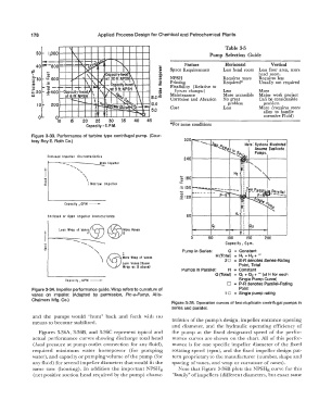
Figure 3-33. Performance of turbine type centrifugal pump. (Cour-
300
tesy Roy E. Roth Co.) Note : Systems IHustrated
Assume Dupllcate
Pumps.
Enclosed Impeller Characteristics
240
..... , Wide Impeller
<,
'
..
" .. \ .....
-e ' \ ';; 180
,: \ Narrow Impeller
.s 150
...,
.,
� 120
Capacity , GPM --
Enclosed or Open Impeller Characteristics 60 H,
Vane;@ @ � ore o, 02
Less Wrap of Vanes
0 50 100 150 200
.. ·-·- .......... Capacity, Gpm.
"D <,
0
,: -, iore Pump in Series: Q = Constant
\ @ Less Vones {Same H (Total) = H 1 + H 2 + "'
Wrap of Vann
20 = S-R denotes Series-Rating
Point, Total
Wrap as B above}
Pumps in Parallel: H = Constant
Q (Total) = 0 1 + 02 + "' (at H for each
Single Pump Curve)
Capacily, GPM -
0 = P-R denotes Parallel-Rating
Figure 3-34. Impeller performance guide. Wrap refers to curvature of Point
vanes on impeller. (Adapted by permission, Pie-a-Pump, Allis- 1 0 = Single pump rating
Chalmers Mfg. Co.)
Figure 3-35. Operation curves of two duplicate centrifugal pumps in
series and parallel.
and the pumps would "hunt" back and forth with no
means to become stabilized. teristics of the pump's design, impeller entrance opening
and diameter, and the hydraulic operating efficiency of
Figures 3-36A, 3-368, and 3-36C represent typical and the pump at the fixed designated speed of the perfor-
actual performance curves showing discharge total head mance curves are shown on the chart. All of this perfor-
(head pressure at pump outlet connection for any fluid), mance is for one specific impeller diameter of the fixed
required minimum water horsepower (for pumping rotating speed (rpm), and the fixed impeller design pat-
water), and capacity or pumping volume of the pump (for tern proprietary to the manufacturer (number, shape and
any fluid) for several impeller diameters that would fit the spacing of vanes, and wrap or curvature of vanes).
same case (housing). In addition the important NPSHR Note that Figure 3-36B plots the NPSHR curve for this
(net positive suction head required by the pump) charac- "family" of impellers (different diameters, but exact same