Page 206 - APPLIED PROCESS DESIGN FOR CHEMICAL AND PETROCHEMICAL PLANTS, Volume 1, 3rd Edition
P. 206

Pumping of Liquids                                       177

                                                                head is twice that of the rated pressure of one pump at the
                                                                designated  flow  rate  (Figure  3-35).  The  pump  casing  of
                                                  Atmosphere    each stage  (particularly the last)  must be of sufficient pres-
                                                  Side          sure  rating  to withstand the developed pressure.


                                                                Pumps in Parallel
          Figure 3-31C.  Double mechanical seal,  two rotary elements against
          common  stationary.  (By  permission,  Fischer,  E.  E.,  Chem  Process-   Pumps  are  operated  in  parallel  ta  divide  the  load
          ing,  Oct.  1983 [24].)                               between two (or more)  smaller pumps rather than a single
                                                                large one, or to provide additional  capacity in a system on
                                                                short notice,  or for many other related reasons.  Figure  3-
                                      , ,  (-                   35 illustrates the operational curve of two identical pumps
                                             Barrier Fluid In
                                                                in  parallel,  each  pump  handling  one half the  capacity  at
                                                  Atmosphere    the system head conditions. In the parallel arrangement of
                                                  Side          two or more pumps of the same or different characteristic
                                                                curves,  the capacities of each pump are added, at the head
                                                                of the system,  to obtain  the delivery flow of the pump sys-
                                                                tem. Each pump does not have to c?JTY  the same flow; but
          Figure  3-310.  Tandem  double  seal.  (By  permission,  Fischer,  E.  E.,   it will  operate  on  its  own  characteristic  curve,  and  must
          Chem.  Processing,  Oct.  1983 [24].)                 deliver the  required head. At a  common  tie  point on  the
                                                                discharge of all  the  pumps,  the head will be  the same for
          the sum of the individual  discharge pressures of the indi-   each pump,  regardless of its flow.
          vidual  pumps.  For identical  pumps,  the capacity is that of   The  characteristic  curves  of each  pump  must be  con-
          one pump,  and the discharge pressure  of the last pump is   tinuously  rising  (right  to  left)  as  shown  for  the  single
          the sum of the individual  heads of each  pump acting as a   pump of Figure 3-35,  otherwise with  drooping or looped
          single  unit.  Thus,  for  two  identical  pumps  the  discharge   curves  they may be two flow conditions for any one head,


                               l             !


                           \
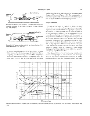
                             "{                              .-   __  -· -  ·-..... ._tfficlency
                                                                _c
                                                                    -
                                                                                 .....
                        Q)  ,d     I',._   ,Head,  ft.  a f  Liquid   ,,./   ...  '!-  --  -.-1   ...........
                               r-,
                        "C                             /    :.,..--            -,
                        "'
                        :i:   .........   I  f'.....r--L   -:   /   ...  7"           A= Axial
                        >-                                                            M  =Mixed
                        u      '   .........     :----_  -;   /                  '
                        c:         l(._       ./        -.,L.                         C  =Centrifugal
                        Q)
                        ·.::;    "    i-   M       /    -
                                                 .,--
                        iE  -·-  ·-  ·-  /;; -·-                �
                                                                   �
                        UJ                ��         ?2  -· -  ·-      :::,... _
                        c.:                                                   ·.-
                                          I//
                        :i:            ./       //                    Rating  I  ;:;:
                        co   �                                         Point   �   ·-.  �
                           ---  r--  �  � /  ira  ke  Horsepower            t   \   [\          I
                                             ,/
                                                  A
                                          i--  u, :M:_
                                   "7
                                 /    �  �  _  .....   c   --                     -             I
                                   "  /-  -·-
                               0             -·--·                            r-.;              I
                           �                                                      �  r---.......   I
                           './/                                                              I  I
                                                         Gallons per minute
          Figure 3-32.  Comparison  of impeller types for centrifugal  pump performance.  (Adapted by permission from Pie-a-Pump,  Allis-Chalmers Mfg.
          Co.)
   201   202   203   204   205   206   207   208   209   210   211