
Page 288 - APPLIED PROCESS DESIGN FOR CHEMICAL AND PETROCHEMICAL PLANTS, Volume 1, 3rd Edition
P. 288
258 Applied Process Design for Chemical and Petrochemical Plants
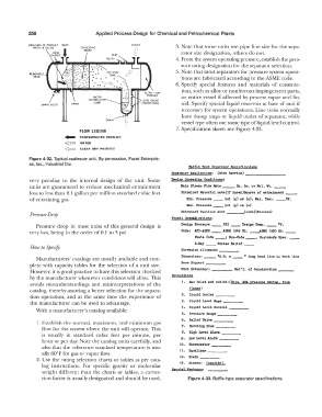
EMULSION OF PRODUCT INLET OUTLET 3. Note that some units use pipe line size for the sepa-
WATER & SOLIDS COALESCING
MEDIA
rator size designation, others do not.
4. From the system operating pressure, establish the pres-
sure rating designation for the separator selection.
5. Note that most separators for pressure system opera-
REMOVABLE
HEAD tions are fabricated according to the ASME code.
6. Specify special features and materials of construc-
tion, such as alloy or nonferrous impingement parts,
WATER or entire vessel if affected by process vapor and liq-
ACCUMULATOR
SWING BOLTS DRAIN 5UMP uid. Specify special liquid reservoir at base of unit if
necessary for system operations. Line units normally
have dump traps or liquid outlet of separator, while
vessel type often use some type ofliquid level control.
7. Specification sheet: see Figure 4-33.
FLOW LEGEND
� CONTAMINATED PRODUCT
�'-:--.-;,i WATER
¢=:J CLEAN DRY PRODUCT
Figure 4-32. Typical coalescer unit. By permission, Facet Enterpris-
es, Inc., Industrial Div.
Bartle :r,pe Separator Spec1r1cationa
Separator .lppl1cat1on1 (Give Sarrtce) --------
very peculiar lo the internal design of the unit. Some Dea1gn Operating Conditions:
units are guaranteed to reduce mechanical entrainment Maln Stream l"lov Rate __ Sp. Gr. or Mol. Wt. __
loss to less than 0.1 gallon per million standard cubic feet Entrained Material rate(U Jmovn)Source or entra1111111ent __
of entraining gas. Min. Preaaure __ psi (g) or (a), Jlax. Temp, __ or.
Max. Pressure __ pe1 (g) or (a)
Entrained Particle a1ze (meah)(H1crona)
Pressure Drop
Veaael 3pectr1cat1ona:
Pressure drop in most units of this general design is Dea1gn Preaaure __ PSI __ Dea1gn Temp. __ or.
very low, being in the order of 0.1 to 3 psi. Coile: .lPI-.1.SME -- .lBIIE 1949 Ed. __ .I.SHE 1950 m. --
State Code __ ; Hon-Code __ , Cuatomei's Spec. __
X-Ra7 __ Stress Rel1et' __
How to Specify
Corrosion allovande ----
D1mena1ons: __ •o.D. x __ • long bend line to bend llne
Manufacturers' catalogs are usually available and com-
plete with capacity tables for the selection of a unit size. Baae SUpport ----
However, it is good practice lo have this selection checked H1at Ex.tractor: , Mat'l. ot Conatructlon _
by the manufacturer whenever conditions will allow. This Connect1ona
avoids misunderstandings and misinterpretations of the 1. Gae inlet and outlet:(S1ze, .I.SA. pressure rat1ne;, tuie
catalog, thereby assuring a better selection for the separa- rlanp;e)
tion operation, and at the same time the experience of 2. Uqu1d outiet ----
the manufacturer can be used to advantage. 3. Uquld Level aage ----
With a manufacturer's catalog available: 4. Uquid Level Control ----
5. Pressure Gsuge ----
6. Reller Valve ----
1. Establish the normal, maximum, and minimum gas
flow for the system where the unit will operate. This 7. Bursting Dlac ----
is usually in standard cubic feet per minute, per 8. High Level Alarm----
hour or per day. Note the catalog units carefully, and 9. Low Level Alarm ----
also that the reference standard temperature is usu- 10. Thermometer ----
ally 60°F for gas or vapor flow. 11. F.qual1zer ----
2. Use the rating selection charts or tables as per cata- 12. Drain ----
13. Others: ( apeei:l'Y)
log instructions. For specific gravity or molecular
weight different than the charts or tables, a correc- 6pec1a1 Features:
tion factor is usually designated and should be used. Figure 4-33. Baffle-type separator specifications.