
Page 286 - APPLIED PROCESS DESIGN FOR CHEMICAL AND PETROCHEMICAL PLANTS, Volume 1, 3rd Edition
P. 286
256 Applied Process Design for Chemical and Petrochemical Plants
Figure 4-27C. Typical fiberbed mist eliminators are available in both
candle and panel configurations. By permission, Otto H. York Co., Inc.
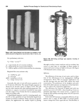
For preliminary selection: Figure 4-28. Wall-wiping centrifugal type separator. Courtesy of
Wright-Austin Co.
Vo= k[(P1 - p,)/Pvl112 ( 4-51)
p, = vapor density, lb/cu ft at actual conditions through a surface contact medium such as excelsior, hay,
PL = liquid density, lb/cu ft at actual conditions cotton or wool bats, or cartridges of fibers similar in
k = 0.40 for up-flow at 0.65 for horizontal flow, for estimating nature and weave to those of Table 4-12A and -12B. Figure
4-32 illustrates some of these types.
Required flow area estimate only,
Efficiency
A = (ACFS)/V0, sq ft
A= area sq ft The efficiency of this type of unit varies, and is a func-
ACFS = actual flow, cu ft/ sec tion of the effectiveness of the impingement baffling
V 0 = design velocity, ft/sec arrangement. About 70% of separator applications can
use the line-type unit; the other 30% require the vessel
Generally, this style of unit will remove particles of 12 construction. The preference of the designer and prob-
to 15 microns efficiently. The typical droplet separator is lems of the plant operator are important in the final selec-
shown for an air-water system in Figure 4-17 A. This will tion of a unit to fit a separation application.
vary for other systems with other physical properties. The The efficiency for removal of liquid and solid sus-
variations in capacity (turndown) handled by these units pended particles is 97-99%+ when handling 15-micron
is in the range of 3 to 6 times the low to maximum flow, particles and larger. For steam service, a typical case
based on k values (33]. would be 90% quality entering steam with 99.9 percent
A liquid-liquid separator used for removing small, usu- quality leaving.
ally 2% or less, quantities of one immiscible liquid from Some units will maintain a reasonable efficiency of sep-
another is termed a coalescer. These units are not gravity aration over a range of 60%-120% of normal perfor-
settlers, but agglomerate the smaller liquid by passing mance rating while other types will not. This flexibility is