
Page 34 - APPLIED PROCESS DESIGN FOR CHEMICAL AND PETROCHEMICAL PLANTS, Volume 1, 3rd Edition
P. 34
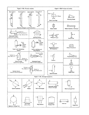
Figure 1-19A.  Process vessels.                     Figure 1-198.  Pumps and solids.

              Plate Column   Packed Column   Spray Column   Pulse Column
                                                                    Feed �
                                                                         � Filtrate
                                                                          Solids
                �                                                                              Vibrating Feeder
                                                                      Batch Centrifuge


                                                                                              [:<  '><'. ·:<  >:]
                         Absorbers, Stripf"rs  and Fractionators                                        t
                                                                       Rotary Feeder       Ribbon  Blender or Conveyor
               � '   ;)- � ::::. �
                                ;'.;,d;om lo
                     Coolant or  Htg.  Medium  Out
              Horizontal  Vessel
             (Jacketed  &  Ag)ated)            Oil-Fired  Heater        Pump (All  Types)
                                                                                                Sump Pump
                                                      Show:
                                                        KW
                               Show:         o    o-fl=}  Voltage
                                KW           o    o     Phase
                                Voltage      o  O       Cycle 5
                                                  O
                                Phase        0    0
                                Cycle 3       0   0                  Reciprocating Pump       Rotary Comprenor
                   Vesse!  with  Immersion   Vessel  wit.h  Electrical   Or Compreuor
                         Heaters                Strip Heaters
                      u

                                                       Medium
               Coolant o,                        *   Coolant or  Htg.                            �
             Htg.  Medium  In   Coolant  or         )��ut              --1                     Proportioning Pump


                                    Out
                      Vertical  Vessel  Htg.  Medium   Horizontal  Vessel   Cyclone                i
                    (Jacketed  &  Agitated)   (Internal  Coils  &  Agitated)                     Agitator

                                  Coolant or                         -D                           2
                               Htg.  Medium  In
                                                Coolant or
                                                Htg.  Medium  Out
                   Vertical  Venel
               (Internal  Coils &  Agitated)                                                    Weigh Scale
                                                                      Bucket Elevator
           !                                     Figure  1-19C.  Storage equipment.
           ������ - ���������������� -.- ���������
                                                                                      ........  ����������-!
               0010,.,, �        +   ,,,0                           �  -fl
           l , 1 1 : .


                                 \'l � e3:                           Horizontal Vessel         �
           I                      ,..                                (Pressure Storage)
           I      Cooler-Condenser     Heater      Heat Interchanger                       Receiver-Surge Tank
           r


                                £WO                                                 a          D


                                    Gas Holder                      Atmospheric     'ere   Tank Car  G-e I
                                   (Wet  or  Dry)    Bag Collector   Storage Tank                     Hopper Bin
             Spherical  �torage Tank
               ������-����������-'-���������'--�������--'L...���������--''--�����  ....