
Page 38 - APPLIED PROCESS DESIGN FOR CHEMICAL AND PETROCHEMICAL PLANTS, Volume 1, 3rd Edition
P. 38
-- Process Planning, Scheduling and Flowsheet Design 23
Key or Principal Process Lines
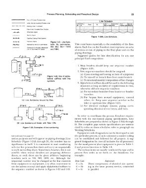
Utility. Service. Auxihary Process Lrees Line Size, Line Sched11le Insulation J Test Specie I
Line
Ne. In. From To Clos• er Code Cede I Prmure, psiQ Rtftlerh
Existmg Lines In a System
I
I
Flow Arrow. lndrcates Flow Directior.
I
- -
Pneumatic Signal
Electric Signal
Figure 1-24A. Line Schedule.
Capillary Tubing {Filled System)
Hydraulic Signal Figure 1-21. Line Sym-
Radioactive, Sonic or Light Signal bols. By permission, This contributes materially to the readability of the flow-
ISA Std. 85.1-1973 sheets. Each line on the flowsheet must represent an actu-
Connect1011 to Process, Mechanical
Link or Instrument Air Supply and 1984. al section or run of piping in the final plant and on the
piping drawings.
Suggested guides for line identification for any one
6"-P-21 2"-LCW-3a
'll---,2-----1, � 1 :,, principal fluid composition:
.
D _ _,
N 21a 1. Main headers should keep one sequence number
. "' (Figure 1-23).
0..
I
� 2. New sequence numbers should be assigned:
I l/2°-P-22b (a) Upon entering and leaving an item of equipment
Figure 1-22. Use of alpha- (b) To take-off or branch lines from main headers
betical suffixes with line
symbols. (c) To structural material composition ofline changes
3. Alphabetical suffixes should be used in the following
situations as long as clarity of requirements is clear,
2'!FW-5 otherwise add new sequence numbers.
(a) For secondary branches from headers or header-
branches
(b) For by-pass lines around equipment, control
(Al Line Numbering Around By-Pass valves, etc. Keep same sequence number as the
inlet or upstream line (Figure 1-23).
l �rd ,·-r:-7! ,. ':7,w-ae sponding identical service items, and lines.
(c) For identical multiple systems, piping corre-
6"-TW-5
2�TW-5
4"-TW-5
In order to coordinate the process flowsheet require-
(CJ) --�--- '1;1•-•: r ments with the mechanical piping specifications, Line
1
Schedules are prepared as shown in Figure l-24A through
(Bl Line Numbering of Header with Take - Offs
D. The complete pipe system specifications are summa-
Figure 1-23. Examples of line numbering. rized by codes on these schedules; refer to paragraph on
Working Schedules.
Equipment code designations can be developed to suit
(text continued from page 18) the particular process, or as is customary a master coding
nation purposes and will appear on piping drawings, Line can be established and followed for all projects. A sug-
Schedule (Figure 1-24A through D), the number has no gested designation list (not. all inclusive for all processes)
significance in itself. It is convenient to start numbering for the usual process plant equipment is given in Table 1-
with the first process flow sheet and carry on sequentially 2 and process functions in Table 1-3.
to each succeeding sheet. Sometimes, however, this is not The various items are usually numbered by type and in
possible when several detailers are preparing different process flow order as set forth on the flowsheets. For
sheets, so each sheet can be given arbitrary beginning example:
numbers such as !00, 300, 1000, etc. Although the
sequential number may be changed as the line connects Item Code Represents
from equipment to equipment, it is often convenient to C-la Three compressors of identical size operat-
use the system concept and apply alphabetical suffixes to C-1b ing in the same process service, connected
the sequence number as shown in Figures 1-22 and 1-23. C-lc in parallel.