Page 36 - APPLIED PROCESS DESIGN FOR CHEMICAL AND PETROCHEMICAL PLANTS, Volume 1, 3rd Edition
P. 36

Process Planning, Scheduling and Flowsheet Design                       21


                                                          Compressors


                                �
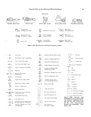
           Horizontal, Motor-Driten   Steam -Driven   Vertica I  , Motor - Driven   Vertical,  Motor-Driven   Rotary  Blower  Motor-Driven


                      &                                     Motor Driven  Sump  Pump   loo  Steam  Driven
                              Turbine  Driven
                              Centrifugal  Compressor
                                                                                         Reciprocating  Pump
                                                      �
                      fu      Engine  Driven  Pump   �      Vertical  Centrifugal   �    Motor  Driven
                                                                                         Reciprocating  Pump
                              (G  =  Gas  or  D  =  Diesel)
                                                            Pump with  Motor
                        ¢     Rotary  Pump         �        Turbine  Driven     �        Motor Driven
                                                            Centrifugal  Pump
                                                                                         Centrifugal  Pump
                                       Figure  1-20A. Special types of descriptive flowsheet symbols.


           --111--    Orifice  P!ate                          Diaphragm  Operated  Butterfly  Valve   0-  Pilot  Light
           -ffi-      Orifice  Plate  in  Quick  Change  Fitting   Diaphragm  Operated  Angle  Valve   6--  Data  to  Computer


                      Venturi  Tube  or  Flow  Nozzle·                                        0-       Computer Set
                                                             Self-Contained  Regulating  Valve
                      Pitot  •ube  or  Pitot  Venturi  Tube
                                                             Double  Diaphragm  Control  Valve   Relay  Function  Designations
                                                                                            Types
                      Turbine  or  Propeller Type  Element
                                                             Hydraulic or  Pneumatic  Piston   L  =  Add
                                                             Operated  Control  Valve
                      Rotameter                                                              D =  Subtract
                                                             Rotary  Motor  Operated  Control  Valve   +   =  Bias
                      Rotameter with  Integral
                      Throttle  Valve                                                        �   =  Extract Square  Root
                                                             Solenoid  Operated  Gate  Valve
                      Chemical  Seal                                                             =  Divide
                      Rupture  Disc  for  Pressure  Relief   Three-Way  Solenoid  Valve      0  =  Multiply
                                                              Latch  Type  With  Manual  Reset
                                                                                             I : j   =  Booster
                      Rupture  Disc  for Vacuum  Relief
                                                             Multiple  Orifice  Plate        �    =  !-ligh  Select
                      Pressure  O' Safety  Valve                                             g)  =  Low  Select
                                                    0-       Locally  Mounted  Instr.       R E V  Rev  =  Reverse
                      Vacuum  Relief  Val�e
         Vac.  "t' Press.   Pressure  and  vacuum  relief Valve   e-  Main  Panel  Mounted  Instr.   EI  P  E/P  =  Potential  to  Pneumatic
                      (Conservation  Vent)
         �                                          e--                                      I/  P  1/P  =  Current  to  Pneumatic
                      Float  Operated  Valve  (LCV)          Local  Panel  Mounted  Instr.   E / I  Ell  =  Potential  to  Current
                                                    0-       Instr.  Mounted  Behind  Panel   Figure  1-208.  Commonly  used
                      Hand  Control  Valve                                              instruments for process instrumenta-
                                                                                        tion flowsheets.  Adapted  by  permis-
                                                    CX)-
                      Diaphragm  Operated  Control  Valve    Instr.  with  Two  Functions   sion,  ISA  Std.  ANSI  ¥32.20-1975,
                      FC  =  Fail  Closed.  FO  =  Fail  Open                           ISA  SS.1-1973,  "Instrumentation
                      Diaphragm  Operated  Control  Valve   Gb-  Heat Traced  Instr.    Symbols  and  Identification,"  Latest
                      with  H andwheel                       S  =  Steam.  E  =  Electric   edition,  1984.
   31   32   33   34   35   36   37   38   39   40   41