
Page 376 - APPLIED PROCESS DESIGN FOR CHEMICAL AND PETROCHEMICAL PLANTS, Volume 1, 3rd Edition
P. 376
344 Applied Process Design for Chemical and Petrochemical Plants
implosion (collapse) of a tank, reactor, other process Table 6-1
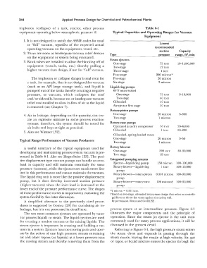
equipment operating below atmospheric pressure if: Typical Capacities and Operating Ranges for Vacuum
Equipment
1. It is not designed to satisfy the ASME codes for total
or "full" vacuum, regardless of the expected actual Lowest
operating vacuum on the equipment, vessel, etc. recommended
suction
Capacity
2. There are none or inadequate vacuum relief devices Type pressure range, ft3 /min
on the equipment or system being evacuated.
3. Block valves are installed to allow the blocking off of Steam ejectors 75 torr 10-1,000,000
equipment (vessels, tanks, etc.) thereby pulling a One-stage 12 torr
Two-stage
higher vacuum than design, if not for "full" vacuum. Three-stage L torr
Four-stage 200 micron*
The implosion or collapse danger is real even for Five-stage 20 micron
a tank, for example, that is not designed for vacuum Six-stage 3 micron
(such as an API large storage tank), and liquid is Liquid-ring pumps
pumped out of the tanks thereby creating a negative 60°F water-sealed
pressure, or vacuum, which collapses the roof One-stage 75 torr 3-10,000
and/or sidewalls, because no or inadequate vacuum Two-stage 40 torr
relief was installed to allow in-flow of air as the liquid Oil-sealed 10 torr
is removed (see Chapter 7). Air-ejector first stage lO torr
Rotary-piston pumps
4. Air in leakage, depending on the quantity, can cre- One-stage 20 micron 3-800
ate an explosive mixture in some process reaction Two-stage 1 micron
systems; therefore, the system should be tested for Rotary-vane pumps
air leaks and kept as tight as practical. Operated as a dry compressor 50 torr 20-6,000
5. Also see Wintner l32]. Oil-sealed 1 torr 50-800
Oil-sealed, spring-loaded vanes
One-stage 20 micron 3-50
Typical Range Performance of Vacuum Producers
Two-stage I micron
A useful summary of the typical equipment used for Rotary blowers
developing and maintaining process system vacuum is pre- One-stage 300 torr 30-30,000
sented in Table 6-1. Also see Birgenheier [33). The posi- Two stage 60 torr
tive displacement type vacuum pumps can handle an over- Integrated pumping systems
load in capacity and still maintain essentially the same Ejector-liquid-ring pump 150 micron 100-100,000
pressure (vacuum), while the ejectors are much more lim- Rotary-blower-liquid-ring 1 torr 100-10,000
pump
ited in this performance and cannot maintain the vacuum. Rotary-blower-rotary-piston 0.001 micron 100-30,000
The liquid ring unit is more like the positive displacement pump
pump, but it does develop increased suction pressure Rotary-blower-rotary-vane 100 micron+ 100-30,000
(higher vacuum) when the inlet load is increased at the pump
lower end of the pressure performance curve. The shapes *l micron = 0.001 torr.
of these performance curves is important in evaluating the +Based on two-stage, oil-sealed rotary-vane design that relies on centrifu-
system flexibility. See later discussion. gal force Lo throw the vanes against the casing wall.
A simplified alternate t.o the previously cited proce- By permission, Ryans and Croll [22].
dures is suggested by Gomez [29) for calculating air in-
leakage, but it is not presented in detail here. process system at an intermediate pressure. Figure 6-1
The two most common ejectors are operated by water illustrates the major components and the principle of
(or process liquid) or steam. The liquid ejectors are used operation. Since the steam jet ejector is the unit most
for creating a modest vacuum or for mixing liquids. The commonly used for many process applications, it will be
steam ejector is important in creating and holding a vac- discussed in the greatest detail.
uum in a system. Ejectors have no moving parts and oper- Referring to Figure 6-1, the high pressure steam enters
ate by the action of one high pressure stream entraining the steam chest and expands in passing through the
air and other vapors (or liquids) at a lower pressure into steam nozzle, leaving the nozzle at high velocity. Air, gas
the moving stream and thereby removing them from the or vapor, or liquid mixture enters the ejector through the