
Page 380 - APPLIED PROCESS DESIGN FOR CHEMICAL AND PETROCHEMICAL PLANTS, Volume 1, 3rd Edition
P. 380
348 Applied Process Design for Chemical and Petrochemical Plants
zero load or shutoff pressure, Reference [18] indicates the
approximate values for evacuation pressures (lowest):
Stage No. in System Lowest Absolute Pressure, mm Hg abs
Single 50
Two 4 to 10
Three 0.8 to 1.5
Suction Four 0.1 to 0.2
Five 0.01 to 0.02
Six 0.001 to 0.003
Single Stage Figure 6-10 is a summary of operating pressure ranges
for a variety of processes and vapor mixtures.
Table 6-1 and Table 6-3 gives the usual industrial appli-
cation ranges for ejector stages.
Figures 6-llA, B, and C indicate the capacity of various
ejector-condenser combinations for variable suction pres-
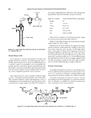
Figure 6-3. Single-stage non-condensing ejector. By permission, sures when using the same quantity of 100 psig motive
C. H. Wheeler Mfg. Co. steam. Each point on these curves represents a point of
maximum efficiency, and thus any one curve may repre-
sent the performance of many different size ejectors each
Vacuum Range Guide
operating at maximum efficiency [1]. Good efficiency may
be expected from 50%-115% of a design capacity. Note
It is necessary to consult manufacturers for final and
specific selections. However, the following guide data is that the performance range for the same type of ejector
reliable and should serve to check recommendations or may vary widely depending upon design conditions.
to specify a system. It is advisable to try to accomplish the
specific operation with as few ejectors as possible, because Pressure Terminology
this leads to the most economical operation and lowest
first cost in the majority of cases. Figures 6-9A, B, and C For design purposes it is necessary to use absolute pres-
are a basic comparison guide for vacuum systems. sures. In plant operation pressures are often used as "vac-
uum." It is important to eliminate confusion before mak-
ing a proper performance analysis. See Tables 6-4 and 6-5.
The ranges shown for various numbers of ejector stages
provide a reasonable operational guide with understand- If pressure is expressed as inches of mercury vacuum,
able variations between various manufacturers, even in the reading of the local barometer ( or a reference barom-
combinations of each manufacturer's specific ejectors used eter) is necessary to establish the absolute suction pres-
to attain lower or upper range of the chart. For example, at sure, or pressure in the vacuum system.
Motive Steam Sino le Sin,;ile Motive Steam
' � --s_,_o_ e Sto,;ie Inlet
__
--��-- Aflercondenser
Suction
(c---:! __
?)
' ( D ) I
+.
Dram
Figure 6-4. Twin single-stage ejectors with surface after-condenser. By permission, C. H. Wheeler Mfg. Co.