
Page 381 - APPLIED PROCESS DESIGN FOR CHEMICAL AND PETROCHEMICAL PLANTS, Volume 1, 3rd Edition
P. 381
Ejectors and Mechanical Vacuum Systems 349
Steam Nozzle
Operating
•
�:;:: � I 1:1�e" Steam
"'"iJf7}
Diffuser .:J [ Air-Vapor
Firs/ J Inlet
Stage
Cooling
Wot er
lnleJ
Discharge
Intercondenser
Operating
Steam
..
Water Discharge
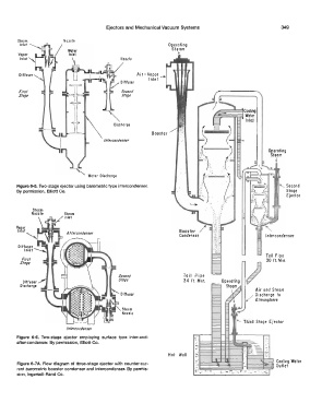
Figure 6-5. Two-stage ejector using barometric type intercondenser. , Second
By permission, Elliott Co. Stage
Ejector
Steam
Nozzle Steam
Inlet
VaP.or
Inlet Booster /
Condenser
Toil Pipe
First 30 ft. Min.
Stage
Toil Pipe
34 ft. Min.
Air and Steam
Diffuser / Discharge to
It' Atmosphere
Steam
Nozzle
/nlercondenser
Figure 6-6. "Two-stage ejector employing surface type inter-and-
after'-condenser. By permission, Elliott Co.
..
....
Hot Well
·. Cooling Water
•.
Figure 6-7A. Flow diagram of three-stage ejector with counter-cur- Outlet
rent barometric booster condenser and intercondenser. By permis-
sion, Ingersoll-Rand Co.