
Page 400 - APPLIED PROCESS DESIGN FOR CHEMICAL AND PETROCHEMICAL PLANTS, Volume 1, 3rd Edition
P. 400
368 Applied Process Design for Chemical and Petrochemical Plants
For ejector design a value of 1.25 times this value is rec- and experience. The objective is to be able to develop reli-
ommended. able specifications for "rough vacuum" equipment. The
Another recommendation based upon years of experi- procedure is [22):
ence is reasonably conservative [14):
1. Estimate air leakage into the system based on possi-
Suction Pressure Allowance for Air ble weld cracks, metal weld, or metal porosity:
In. Hg Abs Leakage, Lbs/Hr
I s P < 10 torr; W'a = 0.026 po.34 yD.60 (6-9)
8 to 15 30 to 40
5 to 8 25 to 30
3 to 5 20 to 25 10 s P < 100 torr; W'a = 0.032 p0.26 yD.60 (6-10)
1 to 3 10 to 20
100 s P < 760 torr; W'a = 0.106 Yo- 60 (6-11)
where P = system operating pressure, torr
For systems with moving sealed parts, make extra V = system volume, cu ft
allowance and consult the seal manufacturer. W' a = air inleakage resulting from metal porosity and
Air leakage into systems operating at or below 0.53 cracks along weld lines, lb/hr
atmosphere, or 15 in. Hg abs, is constant and approxi-
mately independent of the process itself. From atmos-
pheric down to 15 in. Hg, the air leakage increases as the 2. Estimate acceptable air leakages resulting from leak-
pressure decreases. age around static and rotary seals, valves, access
ports, and other items of mechanical nature
required for process operation from the following
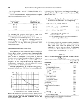
Dissolved Gases Released From Water equations and the specific leak rates 0 indicated in
Table 6-8, which is based on Was; 10 lb/hr.
When ejectors pull non-condensables and other vapors
from a direct contact water condenser (barometric, low
level jet, deaerator) there is also a release of dissolved Table 6-8
gases, usually air, from water. This air must be added to Specific Air Inleakage Rates for Rough Vacuwn, for Use
the other known load of the ejector. Figure 6-22 presents with Equations
the data of the Heat Exchange Institute [1 OJ for the
amount of air that can be expected to be released when 9 = specific leak
cooling water is sprayed or otherwise injected into open Component rate*, lb/h/in.
������-����·
type barometric or similar equipment. Static seals
Alternate, for additional air inleakage calculations are 0-ring construction 0.002
presented by Reference [26) based on industrial studies Conventional gasket seals 0.005
Thermally cycled static seals
t X 200°F 0.005
100 200 X t < 400°F 0.018
I'\. t x 400°F 0.032
... 90 r-, Motion (rotary) seals
r-, Mechanical seals 0.10
", 80 0-ring construction 0.10
-. Threaded connections 0.25
Conventional packing
0.015
<, Access ports 0.020
<, Viewing windows 0.015
<, Valves used to isolate system
r-,
I'- Ball 0.02
Gate
0.04
9 10 11 12 13 14 15 16 17 18 Globe 0.02
Air Released from Water , lbs. Air per Hour per 1,000 gpm. Water Plug-cock 0.01
Valves used to throttle control
Figure 6-22. Dissolved air released from water on direct contact in gas into vacuum system 0.25
vacuum systems. Reprinted by permission, Standards for Direct
Contact Barometric and Low Level Condensers, 4th Ed., Heat *Assumes sonic (or critical) flow across the component.
Exchange Institute, 1957. By permission: Ryans and Croll [22].