
Page 403 - APPLIED PROCESS DESIGN FOR CHEMICAL AND PETROCHEMICAL PLANTS, Volume 1, 3rd Edition
P. 403
Ejectors and Mechanical Vacuum Systems 371
�-00------ INLET
MOTIVE STCAM
IOOSTU UECTOlt
...
•
:!!•
.. o
... 1 -- INTElt • COND •
::, <>
cw
z ..
...
DIIAIN LOOP
IIHAUIT
Figure 6-23. Drying-special three-
stage assembly serving two high vac-
uum dryers. E,y permission, C. H. vacuu• SHELF DltYEltl ltEMOYAL
Wheeler Mfg. Co. PUMP
Steam and Water Requirements 260
I
240
Figure 6-25 presents estimated steam requirements for o/
several ejector systems. Exact requirements can be 220 /
obtained only from the manufacturers, and these will be l v
C..;
based on a specific performance. 200 I v
Figures 6-26A and B give typical good estimating selec- 180 I/
tion curves for single-stage ejectors. Table 6-9 gives evacu- r _.,,.-
-
ation factors. � 160 y
......--
>,
Size selection: locate size at intersection of ejector suc- 'g 140 I ./
tion pressure and capacity on Figure 6-26A. Q. r -
0
.J-
Steam consumption: read values on curves or interpo- � 120 I,- --
""
late. ·;;;
� 100
J Design Po int
(6-20) 80 I
60
Evacuation: I
40
W'm=EV/t (6-21) J
20
I
0 I 2 3 4
Example 6-10: Size Selection. Utilities and Evacuation Absolute Pressure, In. Mercury
Time for Single Stage Ejector
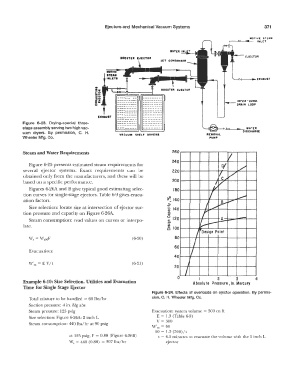
Figure 6-24. Effects of overloads on ejector operation. By permis-
Total mixture to be handled = 60 lbs/hr sion, C. H. Wheeler Mfg. Co.
Suction pressure: 4 in. Hg abs
Steam pressure: 125 psig Evacuation: system volume = 300 cu ft
Size selection: Figure 6-26A: 2 inch L E = 1.3 (Table 6-9)
V = 300
Steam consumption: 440 lbs/hr at 90 psig
\V'm = 60
60 = 1.3 (300)/t
at 125 psig, F = 0.88 (Figure 6-26B) t = 6.5 minutes lo evacuate the volume with the 2-inch L
W, = 440 (0.88) = 397 lbs/hr ejector