Page 399 - APPLIED PROCESS DESIGN FOR CHEMICAL AND PETROCHEMICAL PLANTS, Volume 1, 3rd Edition
P. 399

Ejectors and Mechanical Vacuum Systems                             367


                               8  0                                                            I,
                               6  0
                               5  0
                               4  0
                                3  0
                           a:
                           ::::,   2  0
                           0
                           :I:
                           a:
                           w
                           a.   10.  0
                           en   8. -
                           c
                                 v
                           z   6. 0
                           ::::,
                               5.  0
                           �   4. 0
                           Ji   3. 0
                           �   2.0
                           <(
                           w
                           ...J
                           a:
                           ct
                           :::e       ,,        ..       /
                           ::::,   06  .  -/'-;'-if-t-+-�,�l-++-f-++7"'!-+--+-�1-++-,1-+�-H---+--+-�l-+f-...l��+.I
                                   �
                           :::e   O.Sh...,..+--+-+.,,....,..1-+-+-+-+-+.K- �� -+--+--+--+-+-t-+-++.i...,. � -+--l.-1-+-i-. �� .....  M-1

                                         7

                           �   o.4t--+ ��  ,"'f--+- � -+4,, ���.....  --1�+-+-1-+-+--+-f,,,44-1��-1--1--1-"--l-1--1-�1-&-""
                                    ........  i'- / t-j,,,..f-+- '4- " -+-+-+.++
                           �   0.31--/'       ��        � -+--+--+--+-+-t-+-++.i  .....  �-+--ll,....j�..J.,.i��-'-�
                                  /
                               0.1 ............  _.._._  ....................  L..lo.J..L.L...-....L.-"'....L.-'-'  ..............  �.u.iL...-...i..-'--'--'-'  ......  J...l-'-.i..&.I
                                  0     0   000000           0   000000            0   000000
                                        C\I   C')  'St  IO  «)  CO  O   0   000000   0   000000
                                                             C\I   C')'SflOCOCOO   O   000000
                                                                            ,-     C\I   C'l  'St  IO  CO  CO  O
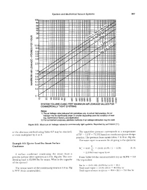
                                   SYSTEM VOLUME-CUBIC FEET MAXIMUM AIR LEAKAGE VALUES FOR  .,....
                                   COMMERCIALLY TIGHT SYSTEMS
                                    Notes:
                                    1.) The air leakage rates indicated are guidelines only.  In actual  field practice, the air
                                      leakage may be significantly larger or smaller depending upon the condition of seat-
                                      ing, maintenance factors, and application.
                                    2.) For comparison purposes, alternate methods of air leakage estimation may be used.

                         Figure  6-21. Maximum air leakage values for commercially tight systems.  Reprinted  by permission  [11 ].

            or the alternate method using Table 6-7 may be checked,   The  saturation  pressure  corresponds  to  a  temperature
            or even multiplied by 2  or 3.                       of79°  - 7.5°F =  71.5°F,  based on condenser-ejector design
                                                                 practice.  The  pressure  from steam tables= 0.78 in. Hg abs.
                                                                    The water  vapor to saturate tl1e air going to the ejector is:
            Example 6-9:  Ejector Load For Steam Surface
            Condenser                                                         pv
                                                                    w'  =  0.62  -  =  (0.62)  (0.78)/(l - 0.78)   (6-  8)
                                                                      \'      p
                                                                               a
                                                                       =  2.19 lbs water vapor/lb air
              A  surface  condenser  condensing  the  steam  from  a
            process  turbine drive operates at 1.0 in.  Hg abs. The con-   From Table 6-6 the recommended dry air SCFM  =  5.0
            densing load  is 85,000 lbs/hr steam.  What is the capacity   The equivalent
            of the ejector?
                                                                    lbs/hr =  (5.0)  (60)  (0.075  lb/  cu ft)  = 22.5
              The  temperature  of the condensing steam at 1.0 in.  Hg   Total water vapor= (2.19)  (22.5)  = 49.4 lbs/hr
            is 79°F  (from steam-tables).                           Total  vapor  mixture to  ejector =  49.4 + 22.5  =  71.9 lbs/hr
   394   395   396   397   398   399   400   401   402   403   404