
Page 504 - APPLIED PROCESS DESIGN FOR CHEMICAL AND PETROCHEMICAL PLANTS, Volume 1, 3rd Edition
P. 504
470 Applied Process Design for Chemical and Petrochemical Plants
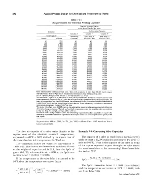
Table 7-14
Requirements for Thermal Venting Capacity
Thermal venung Capacity
(cubic feet of free air" per hour)
Outbreathing (Pressure)
Column I
Column zh Column 3' Column 4•
Tank Capacity lnbreathing Flash Point;,. Flash Point <
Barrels Gallons (Vacuum) IOOF (37 78C) IOOF (37.78C)
60 2.500 60 40 60
100 4.200 100 60 100
500 21.000 500 300 500
1.000 42,000 1,000 600 1.000
2.000 84,000 2.000 1.200 2.000
3.000 126.000 3.000 1,800 3.000
4.000 168.000 4.000 2.400 4.000
5.000 210.000 5.000 3.000 5.000
10.000 420,000 10.000 6.000 10.000
15.000 630.000 15.000 9.000 15.000
20.000 840,000 20,000 12,000 20.000
25,000 1.050.000 24,000 15.000 24.000
30,000 1,260,000 28,000 17.000 28.000
35.000 1.470,000 31.000 19.000 31.000
40,000 1,680,000 34.000 21.000 34.000
45.000 1,890,000 37 ,000 23,000 37 .000
50,000 2,100.000 40.000 24.000 40.0\JO
60,000 2,520,000 44,000 27 ,000 44.000
70,000 2.940.000 48,000 29,000 48,000
80,000 3,360,000 52.000 31.000 52.000
90,000 3, 780,000 56,000 34.000 56,000
100,000 4,200.000 60.000 36.000 60.000
120,000 5.040.000 68.000 41.000 68.000
140,000 5.880,000 75,000 45.000 75.000
160,000 6,720.000 82,000 50,000 82.000
180,000 7,560,000 90.000 54.000 90.000
NoTE: Interpolate for intermediate tank sizes. Tanks with a capacity of more than 180.000 barrels require
individual study. Refer to Appendix A for additional information about the basis of this table.
• At 14. 7 pounds per square inch absolute (1.014 bar) and 60 F (15.56 C).
"For tanks with a capacity of 20.000 barrels or more. the requirements for the vacuum condition are very close
to the theoretically computed value of 2 cubic feet of air per hour per square foot of total shell and roof area. For
tanks with a capacity of less than 20.000 barrels. the requirements for the vacuum condition have been based on
I cubic foot of free air per hour for each barrel of lank capacity. This is substantially equivalent to a mean rate of
vapor-space-temperature change of I 00 F per hour.
'For stocks with a flash point of 100 For above. the outbreathing requirement has been assumed 10 be 60 percent
of the inbreathing requirement. The tank roof and shell temperatures cannot rise as rapidly under any condition
as they can drop. for example, during a sudden cold rain.
•For stocks with a flash point below 100 F, the outbreathing requirement has been assumed 10 be equal to the
inbrearhing requirement to allow for vaporization al the liquid surface and for the higher specific gravity of the
tank vapors.
By permission, API Std. 2000, 3rd Ed.,Jan. 1982, reaffirmed Dec. 1987, American Petro-
leum Institute (26].
The free air capacity of a valve varies directly as the Example 7-9: Converting Valve Capacities
square root of the absolute standard temperature,
expressed as 460°F + 60°F, divided by the square root of The capacity of a valve as read from a manufacturer's
the valve absolute inlet temperature in °Rankine. table or chart is 45,000 cubic feet per hour of.free air ( 14. 7
psia and 60°F). What is the capacity of the valve in terms
The correction factors are noted for convenience in
Table 7-16. The factors are determined as follows: If mol- of the vapors expected to pass through the valve under
ecular weight of vapor in tank is 26.1, then the SpGr of the rated conditions at the same setting? If methanol is in
gas = 26.1/29, referenced to air, = 0.90; so the SpGr cor- the tank at 55°F
rection factor = (0.90)� = 0.9486.
32.04 M .W. methanol
If the temperature at the valve inlet is expected to be SpGr = -------- = 1.104
50°F, then the temperature correction factor 29
The SpGr correction factor = 1.0518 (interpolated)
(460+60) 112 ( � )112 and the temperature correction at 55°F = 1.0018; both
= = 020 = ( 1.0196) 1 = 1.00975 are from Table 7-16.
1 2
460 + 50 510
(text continued on page 471)