Page 508 - APPLIED PROCESS DESIGN FOR CHEMICAL AND PETROCHEMICAL PLANTS, Volume 1, 3rd Edition
P. 508

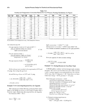
474                      Applied Process Design for Chemical and Petrochemical Plants

                                                           Table 7-16
                      Gravity and Temperature Correction Factors for Low Pressure Venting Calculations for Vapors
            Sp. C:r.  of Gas.   Sp.  Gr.   Sp. Gr.  of GH   Sp. Gr.   Temp.   Factor   Temp.   F1ctor   Temp.   F1ctor
             AIR=  1.00   Factors   AIR=  1.00   Factors   1•r1             (•F)                 (0 f)
                .20      .447      1.10     1.050       5        1.0575      70       .9905      200      .8932
            ---  -------  -  ---  -  -  -   ·- --- ·-                 --   ----   ,.   -  ----1----  -·  ---·
                                         --
                .30      .548      1  .20   1.095       10       1.0518      80       .9813      220
            --------·-  -  ·---·-  -··
                .40      .632      1.30     1.141       15       1.0463      90       .9723      2.«I     .8619
                               -  -·  -·-·--·-- --  -  -·                                -·---  -   -·  ---·  - -------
                .50      .707      1.40     1.185       20       1.0408     100       .9638      260      .8498
            -�-----·---·--  f-  -------  .  -   --------  -  -                      ---   -·-
                .60      .775      1.50     1.223       25       1.0355     110       .9551      280      .8383
            ---·-------  - ---------  --   ---   ·-                      ----  -- -··
                              -·
                .65      .806     1  .60    1.265      30        1.0302     120       .9469      300      .8272
            ---------·  ------  -----  --                                           ·--   ·---
                .70      .837     1.70      1.305       35       1.0249     130       .9388               .8165
            ----- ··------- ,--- ··--·----
                .75      .866     1.80      1.340       40       1.0198     140       .9309      340      .8063
                   -··--------  ..   -         ---  ------  ---···  -  ·-  -
                .80
                         .894
            -----·  -----------    1  . 90   1.380      45       1.0147     150       .9233      360      .7963
                                                                                      .9158
                                  2.00
                                                                            160
                .85
                         .922
                                                                 1.0098
                                            1.412
                                                        50
            ---------  -·---           ----  ·--------  ----·----------   -- -  ---  -  ···-···----···--   380   .7868
                .90      .949      2.50     1.581       55       1.0048     170       .9084      400      .7776
            ---------·  --  ---  -   - ----  -··. ----  -  -- - -----   ·-  -·  --  ·-  ------.
                                                             --- --  -  -
                .95      .975     3.00      1  .731     60       1  .0000   180       . 9014     420      .7687
                ----------  ·----·---·------·  -                                                          ······---·-
               1.00      1.000     3.50     1.870
                                     -- -----  -  ·---·                                                    ··---
               1.05      1.025     4.00     2.000
            By permission, Groth Equipment Corp., Tank Equipment Division.
            (text continued  from page 470)                         SpGr correction  =  (2.69)  1 =  1.64
                                                                                          1 2
              Free gas capacity of  valve (at 14.7 psia and 60° F  =   Temperature correction  =  0.9551 from Table 7-16
                 (free air capacity)  (temp.  corr.  factor)        The volume at standard conditions of 14. 7 psia and 60°F:
                                                        (7 - 52)
                      (SpGr correction factor)
                                                                       _      ( 460 + 60 )  ( 15.  7)
                                                                                        --  = 48,717 cu ft/hr
              Free air capacity of  valve  =                        =  (.'.>0,000)   ( 460 + 11 0 )  (14. 7 )
                 (free gas capacity)  (SpGr co1T factor)
                                                        (7-53)
                     temperature corr.  factor                      Free air capacity of valve at same setting:
                          .          (45,000)  (1.0)
              Free gas capacity of  valve  =
                                        1.0518                        ( 48, 717) ( 1.64)   83,651  SCFH
                                                                          0.9551
                                   =  42, 783 SCFH at 60° F
                                     and 14. 7 psia              Example 7-11: Storing Benzene in Cone Roof  Tank
              If this volume were needed to be expressed at 55°F and   A 26,000 gallon outdoor vertical  storage  tank contains
            1.5  psig,  then using the gas laws:                 benzene. The tank is not insulated, but has a dike around
                                                                 it with a volume equal  to one-and-a-half times the volume
              Actual  flowing volume at 55°F and 1.5  psig       of the tank.  Size  15' diameter  X  20'.  Tank does  not have
                                                                 weak roof.  Temp.  =  60°F,  pressure  =  14.7 psia.
                              460   55      7
              =  42, 783 SCFH  (   +   )   0  4-  )                 Data:  Flash point of benzene: <  100°F
                (           )  ( 460 + 60)  (14.7 + 1.5)
                                                                        Latent heat of  vaporization:  169 BTU/lb
                                                                        Tank size  (nominal): 15' diameter and 20' high
              = 38,448  cu ft/hr
                                                                        Operating pressure:  1.5 oz/in. 2
                                                                        Maximum allowable tank pressure:  3.5  oz/in. 2
            Example 7-10:  Converting Required Free Air Capacity
                                                                        Maximum allowable vacuum:  1.0 oz/in. 2
              The capacity of a relief  valve for a  tank has been calcu-   Relief  valve settings:
            lated  to  be 50,000  cu  ft/hr at  l l0°F and  1.0  psig,  with a   (1)  For pressure:  2.0 oz/in. 2  2
                                                                           (2)  For vacuum:  0.5 oz/in.
            benzene vapor.  Determine the required free air capacity.   Filling rate:  350  gpm  (max)
              For benzene:  MW  =  78.11
                                                                        Draw-out rate  (emptying): 250 gpm
                                                                    A.  Normal venting requirements
                     78.11
              SpGr = --  = 2.69                                       1. Pressure:  filling
                      29
                                                                        Rate  =  (350 gpm)  (60)  =  21,000 gal/hr
   503   504   505   506   507   508   509   510   511   512   513