
Page 503 - APPLIED PROCESS DESIGN FOR CHEMICAL AND PETROCHEMICAL PLANTS, Volume 1, 3rd Edition
P. 503
Applied Process Design 469
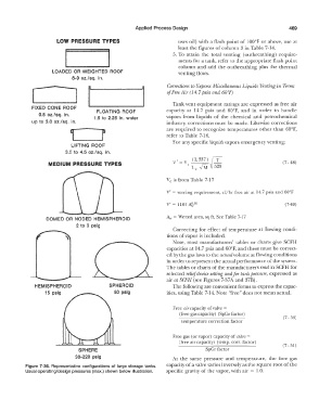
LOW PRESSURE TYPES uses oil) with a flash point of I00°F or above, use at
least the figures of column 3 in Table 7-14.
5. To attain the total venting (outbreathing) require-
ments for a tank, refer to the appropriate flash point
column and add the outbreathing plus the thermal
LOADED OR WEIGHTED ROOF venting flows.
8-9 oz./sq. In.
Corrections lo Express Miscellaneous Liquids \lenting in Terms
[ J of Free 1lir ( 14. 7 psia and 60°F)
Tank vent equipment ratings are expressed as free air
FIXED CONE ROOF capacity at 14. 7 psi a and 60°F, and in order to handle
FLOATING ROOF
0.5 oz./sq. in. 1.5 to 2.25 In. water vapors from liquids of the chemical and petrochemical
up to 3.0 oz./sq. In. industry, corrections must be made. Likewise corrections
are required to recognize temperatures other than 60°F,
refer to Table 7-16.
For any specific liquid vapors emergency venting:
LIFTING ROOF
3.5 to 4.5 oz./sq. in.
v: = v (1,337) rT
MEDIUM PRESSURE TYPES (7- 48)
c i., ,f'M V 520
Ve is from Table 7-17
V' = venting requirement, cf/hr free air al 14.7 psia and 60°F
V' = 1107 A?,: 82 (7-49)
A_,, = Wetted area, sq ft, See Table 7-17
DOMED OR NODED HEMISPHEROID
2 to 3 psig
Correcting for effect of temperature at flowing condi-
tions of vapor is included.
Note, most manufacturers' tables or charts give SCFH
capacities at 14. 7 psia and 60°F, and these must be correct-
ed by the gas laws to the actual volume at flowing conditions
in order to represent the actual performance of the system.
The tables or charts of the manufacturers read in SCFH for
selected relief device setting and for tank pressure, expressed as
air al SCFH (see Figures 7-37 A and 37B).
HEMISPHEROID SPHEROID The following are convenient forms to express the capac-
15 psig 50 pslg ities, using Table 7-14. Note "free" does not mean actual.
Free air capacity of valve=
(free gas capacity) (SpGr factor)
(7 - 50)
temperature correction factor
Free gas (or vapor) capacity of valve=
(free air capacity) (temp. corr. factor)
(7 - 51)
SPHERE SpGr factor
30-220 pslg At the same pressure and temperature, the free gas
Figure 7-36. Representative configurations of large storage tanks. capacity of a valve varies inversely as the square root of the
Usual operating/design pressures (max.) shown below illustration. specific gravity of the vapor, with air = 1.0.