
Page 53 - APPLIED PROCESS DESIGN FOR CHEMICAL AND PETROCHEMICAL PLANTS, Volume 1, 3rd Edition
P. 53
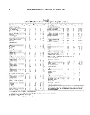
38                        Applied Process Design for Chemical and Petrochemical  Plants


                                                             Table 1-9
                                   Estimated Man-Hours Required for Equipment Design  [7]  (updated)

              Type of  Equipment   ¥Design  **Computer  rlChecking  Total M-H   Type of  Equipment   "Design  **Computer  °Checking   TotaliW-H
                                                            -----�
              HEAT EXCHANGERS:                                     DISTILLATION  (TRAY):
              Solvent cooler       30             3      33        Organic-tray-by-tray  .............. 50   (12)   25   75  (12)
             Tank heating coil      4             2       6        Organic-tray-by-tray  .............. 40   (12)   64   104  (12)
             Caustic cross exchanger   32   (])   6      38        Dernethanizcr-c-tray-by-tray  .... 31   (15)   22   53  (15)
              Caustic cooler        8    (2)      2      10  (2)   Organic-tray-by-tray  .............. 35   (7)   4   46   (7)
              Oil cross  exchanger   32   (3)     5      37  (3)   Organic-tray-by-tray  .............. 10   (5)   5   15   (5)
              Gas cooler            8    (3)      4      12  (3)   Organic-tray-by-tray  ..............  5   (6)   3   II   (6)
              Compressor gas                                       Organic-e-tray-by-tray  ..............  2   (2)   2   4   (2)
               afrercooler          8    (2)      I       9   (2)   De-ethanizer ............................ 24   (12)   15   39  (12)
              Slurry cooler        32    (4)      8      40  (4)   Dcmethanizer .......................... 30   (15)   15   45  (15)
              Finned tube  exchanger   15         4      19        Organic-includes tray
              Gas cooler            4    (])      I       5   (1)    layout  ................................... 24   (15)   28   52  (15)
                                                                   Organic-includes tray
              CONDENSERS:                                            layout ................................... 38   (20)   10   48  (20)
              Steam                 7    (2)              7   (2)
              Organic               6    (2)      2       8   (2)   PUMPS
              HCI  organic         10    (5)     11      21   (5)   System   ······································   8   (2)   6   14   (2)
              Organic               6    (2)      2       8   (2)   Single  .......................................  1.5   (2)   0.5   2  (2)
              Finishing             4    (1.5)    1.5     5.5  (1.5)   Single  .......................................  1   (1)   I   2   ( I)
                                                                    Single   ·······································   3   (I)   3   6   (I)
              PARTIAL CONDENSERS:
              Organic-air          10    (3)      2      12  (3)    RECIPROCATING COMPRESSOR:
              Organic-air          20    (3)      4      24   (3)   BHP,  temperature and  ...........  3      3
              Organic;---air_      �O    ( 4)    14      44  (4)   Data for vendor rating  ............  6   2   8
              Inorganic=-air       aO    (4)     20      70  (4)    CENTRIFUGAL COMPRESSOR:  About the same as
              REBOILERS  (THERMOSIPHON):                            Reciprocating above.
              Organic-steam        16                    16        PROCESS LINE SIZES:
              Organic-steam        20    (3)             25  (3)    Single                     (0.5)    0.5    1.5  (0.5)
              Organic-steam        14     (3)            14  (3)    Single               0.5   (0.5)    0.5    I   (0.5)
              Organic-steam        10    (3)      5      15   (3)   System, 22 lines     20    (3)      9      29   (3)
              Organic-steam        16     (3)     6      22  (3)   Air header for plant   .4.5   (3)    2      6.5  (3)
              Organic-steam        14    (3)      5      24   (3)
              Orgauic-steam         4    (0.5)            4.5  (0.5)   SAFETY VALVES:
              Organic-steam         5     (1)             6   (1)   Single                2             2      4
              Orgauic-steam         4     (1)             5   (1)   Single                1             I      2
              Organic-steam         5     (0.5)           6  (0.5)
              Organic-steam         5     (O . .'>)       6  (0.5)   STEAM TRAPS:
                                                                    System of 4           3             1      4
              REBOILERS  (FORCED CIRCULATION):                      Single                0.75          0.25    1
              Organic-steam        25     ( 4)   10      35   (4)   Single                1             1      2
              Organic-steam        19     (4)     8      27   (4)
              Organic-steam         6     (1)     3       9   (1)   MISCELLAi'<EOUS TANKS,  DRUMS,  ETC.:
              Organic-steam         6     (2)     3       9   (2)   Condensate level drum   0.5         0.5     I
                                                                    Steam flash drum      6             3      9
              DISTILLATION  (PACKED):                               Storage Lank          2                    2
              Carbonating tower    25     ( 4)   10.5    35.5  (4)
              Gas cooler           20     ( 4)    8      28   (4)   MATERIAL BALANCES:
              Gas cooler           25     (6)     7      32  (6)    Depends on  size of system.
              Cooling               16    (5)    22      38  (5)
              Gas scrubber         24     (6)     4      28  (6)    Note: The man-hours listed in this table included collection of needed
              Gas scrubber          12    (6)     8      20  (6)    physical and other data and preparation of a specification or summary
              Vent gas scrubber     5     (2)     1.5     6.5  (2)   of the requirements.
              *Using desk electronic calculators, not programmed.
              **Programmed computer.  Represents data input plus calculation time,  sometimes multiple.
              CJ Checking only for "Design" calculations.
              (  )Alternate calculations by programmed computer.