
Page 78 - APPLIED PROCESS DESIGN FOR CHEMICAL AND PETROCHEMICAL PLANTS, Volume 1, 3rd Edition
P. 78
62 Applied Process Design for Chemical and Petrochemical Plants
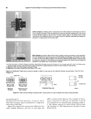
Orifice flanges are widely used in conjunction with orifice meters for measuring the rate of
flow of liquids and gases. They are basically the same as standard welding neck, slip-on and
screwed flanges except for the provision of radial, tapped holes in the flange ring for meter
connections and additional bolts to act as jack screws to facilitate separating the flanges for
inspection or replacement of the orifice plate.
Blind flanges are used to blank off the ends of piping, valves and pressure vessel openings.
From the standpoint of internal pressure and bolt loading, blind flanges, particularly in the larg-
er sizes, are the most highly stressed of all American Standard flange types; however, since
the maximum stresses in a blind flange are bending stresses at the center, they can safely be
permitted to be higher than in other types of flanges.
1.) In Tube Tums tests of all types of flanged assemblies, fatigue failure invariably occurred In the pipe or in an unusually weak weld, never in the flange proper.
The type of flange, however, and particularly the method of attachment, greatly influence the number of cycles required to cause fracture.
2.) ANSI 816.5-1961-Steel Pipe Flanges and Flanged Fittings.
3.) ASME Boller and Pressure Vessel Code 1966, Section I, Par. P-300.
Figure 2-6. Continued. Forged steel companion flanges to attach to steel pipe by the methods indicated. By permission, Tube Turn Tech-
nologies, Inc.
Male to Male Male te Female
Flanged Joint Flanged Joint
A11ambled Ring Joint
Tongue & Grove Joint Gaskets
(uaee flat gasket)
Figure 2-7. Most common flange connection joints. Cross section of a pair of flanges with bolts to draw joint tight.
(uxt continued from page 59) (IPS), nominal inside diameter. One example of dimen-
chemical/petrochemical industries, except for instru- sional comparison for IPS pipe for Schedules 5 and 10
ment lines (sensing, signal transmission) or high pres- are compared to one standard scale of tubing in Table 2-
sures above 2,000 psig. 1. The tubing conforms to ANSI/ ASTM A-403-78 Class
Figure 2-9 compares the measurement differences for CR (stainless) or MSS Manufacturers Standard Society
tubes (outside diameter) and iron or steel pipe size SP-43, Sch 5S.