
Page 80 - APPLIED PROCESS DESIGN FOR CHEMICAL AND PETROCHEMICAL PLANTS, Volume 1, 3rd Edition
P. 80
64 Applied Process Design for Chemical and Petrochemical Plants
TUBE OD IPS
...
•
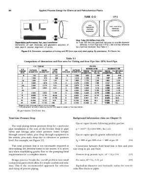
Dependable performance; fast, easy installation How Tube OD Differs from IPS
In Tube OD the size specified indicates its outside diameter
Uniformity of wall thickness and geometric accuracy of ... whereas in Iron Pipe Size (I.PS ), the size has reference
ends permit precise alignment of joints. to a nominal diameter. See Table 2-1.
Figure 2-9. Dimension comparison of tubing and IPS (iron pipe size) steel piping. By permission, Tri-Clover, Inc.
Table 2-1
Comparison of dimensions and flow area for Tubing and Iron Pipe Size (IPS) Steel Pipe.
OD TUBING IPS PIPE
OD FLOW OUTSIDE SCHEDULE tlS SCHEDULE 106
OUTSIDE
INSIDE
IPS
TUBING DIAMETER DIAMETER• AREA PIPE SIZE DIAMETER INSIDE FLOW AREA INSIDE FLOW AREA
SIZE SO.IN. DIAMETER SO. IN. DIAMETER SO.IN.
" .750 .625 .307 % 1.060 .920 .665 .884 .814
1 1.000 .870 .595 1 1.315 1.185 1.10 1.097 .!Mtl
1i. 1.500 1.370 1.47 1% 1.900 1.770 2.46 1.882 2.22
2 2.000 1.870 2.75 2 2.376 2.246 3.96 2.167 3.66
2� 2.500 2.370 4.41 2% 2.876 2.709 6.76 2.836 6.45
3 3.000 2.834 6.31 3 3.!500 3.334 8.73 3.280 8.38
3% . . . . . . ... 3% 4.000 3.834 11.66 3.780 11.10
4 4.000 3.834 11.56 4 4.500 4.334 14.75 4.280 14.26
• 8.000 6.782 26.26 8 8.826 8.407 32.24 8.367 31.76
8 8.000 7.782 47.56 8 8.826 8.407 66.6 8.329 64.5
10 10.000 9.732 74.4 10 10.760 10.482 88.3 10.420 85.3
12 12.000 11.732 108. 12 12.750 12.438 121. 12.390 120.
'Biiied on well thlckn"' lltted on following pes,11.
•' lndlc•tet gr•t•r l•tltud• In 1etectlng lln• tlze with capacity clotest to flow requi,.ment.
By permission Tri-Clover, Inc.
Total Line Pressure Drop Background Information (Also see Chapter 3)
Gas or vapor density following perfect gas law:
The total piping system pressure drop for a particular
pipe installation is the sum of the friction drop in pipe p = 144 P' (T)(l544/MW), lbs/cu ft (2-5)
valves and fittings, plus other pressure losses (drops}
through control valves, plus drop through equipment in Gas or vapor specific gravity referred to air:
the system, plus static drop due to elevation or pressure
level. For example, see Figure 2-2. Sg = MW of gas/MW of air = MW of gas/29 (2-6)
This total pressure loss is not necessarily required in Conversion between fluid head loss in feet and pres-
determining the frictional losses in the system. It is neces- sure drop in psi, any fluid:
sary when establishing gravity flow or the pumping head
requirements for a complete system. Pressure drop, pounds/sq in., �p = h1.p/144 (2-7)
Design practice breaks the overall problem into small For water, �p = hL/2.31, psi (2-8)
component parts which allow for simple analysis and solu-
tion. This is the recommended approach for selection Equivalent diameter and hydraulic radius for non-cir-
and sizing of process piping. cular flow ducts or pipes