
Page 98 - APPLIED PROCESS DESIGN FOR CHEMICAL AND PETROCHEMICAL PLANTS, Volume 1, 3rd Edition
P. 98
82 Applied Process Design for Chemical and Petrochemical Plants
Nozzles and Orifices [3] � = ratio of small to large diameter orifices and noz-
zles and contractions or enlargements in pipes
These piping items shown in Figures 2-17 and 2-18 are
important pressure drop or head loss items in a system
and must be accounted for to obtain the total system pres- For discharging incompressible fluids to atmosphere,
sure loss. For liquids: take C values from Figures 2-17 or 2-18 if hL or L'1P is taken
as upstream head or gauge pressure.
q = c'A � 2g(144)(i'iP)/p = c'A[2ghL ]112 (2-46)
For flow of compressible fluids use the net expansion
factor Y (see later discussion) [3]:
where q = cubic ft/sec of fluid atjwuring conditions
C' = flow coefficient for nozzles and orifices
q = YC' A [2g (144) (i'iP)/p]ll 2 (2-18)
C' = Cd IF- � 4 , corrected for velocity of
approach (2- 47)
where Y = net expansion factor for compressible flow
through orifices, nozzles, and pipe.
Note: C' = C for Figures 2-17 and 2-18, corrected for velocity
of approach.
C' = flow coefficient from Figures 2-17 or 2-18. When
Cd = discharge coefficient for nozzles and orifices
hL = differential static head or pressure loss across discharging to atmosphere, P = inlet gauge pres-
flange taps when C or C' values come from Figures sure. (Also see critical flow discussion.)
2-17 and 2-18, ft of fluid. Taps are located one
diameter upstream and 0.5 diameter down from
the device. For estimating purposes in usual p1pmg systems, the
A = cross section area of orifice, nozzle or pipe, sq ft values of pressure drop across an orifice or nozzle will
h = static head loss, ft of fluid flowing range from 2 to 5 psi. For more exact system pressure
i'iP = differential static loss, lbs/sq in. of fluid flowing, drop calculations, the loss across these devices should be
under conditions of hL above calculated using some size assumptions.
�-
1.20 0.
I.II
i..,1-"'
/ - D.
1.16
/ � -�
i---
.,,.... ... D.
., � ..,,. ...
1.12 -- D.
/ - .s
-
-
I.ID
..,,. .......... -- 0.6S �
-
-: ..,,. .....
1.08 -: ,/ -- om ill
Flow- 1.06 -- ..,,. - D .!O O
4>
.> v -- - 0. us�
l.04 V" ..... D � �
... - �- .... � ..... 1,,-" -- D . IO o
1.02 - -- D. 45 -�
V"
I ,, � i...-- i--- - D. 40 ::
1.00 .. --- D JO
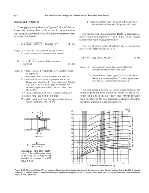
Example: The flow coeffi- 0.98 � [,,::::;: ......... :;:::. ..... ' G.211
cient C for a diameter ratio ..... � �
(, of 0.60 at a Reynolds 0.96 ... ; .. �
number of 20,000 (2 x 10⁴) 0.94 ,
equals 1 .03.
OJ 2
2 6 8 10' 2 6 8 10• 2 6 I Ill"
R, - Revnolds Number based on d 2
Figure 2-17. Flow coefficient "C" for nozzles. C based on the internal diameter of the upstream pipe. By permission, Crane Co. [3]. Crane ref-
erence [9] is to Fluid Meters, American Society of Mechanical Engineers, Part 1-6th Ed., 1971. Data used to construct charts. Chart not copied
from A.S.M.E. reference.