Page 96 - APPLIED PROCESS DESIGN FOR CHEMICAL AND PETROCHEMICAL PLANTS, Volume 1, 3rd Edition
P. 96

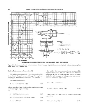
80                       Applied Process Design for Chemical and Petrochemical Plants
                 �·     I   I          I   I   I   I  _..._  I   I   I   I   I   I   I   I   I   I   I   I   I   I   I   I   I   I   I_
                                                 I
                             I
                                                                 -
                                                              -
               1.2   I      �f.o  ,  I   I   I              I   I   I            I                           -
                 ".'°  ••  I   o.�o  I   1   � . 1 30   1   o.�o . i  �� 1 s )   - ........ .. UPPER  LIMIT
                 .__        02  -  D,)/2 L   �  /                                                            -
               1.1   .__                                              --     -                               -
                                       �  '                        -      ...  '                     --   .__ ,_
                                                                              -  -
                  -I                  IJ'       ......  ---  --       - -  ,.._  ....   �   - - -  1--
                                                       ,.  ,-·  ...
               1.0                                  "I  -·
                  -I               I          /                                                           -  -::
                  -;                      �"  '   I   I   I   I   I   I   I   I   I   I   I   I   I   I   I   I   I   I   I   I   I   I   ,-
               0.9                I  '   .,                                                                I
                  '"i                   "      -     70   80   90   100   110   120   130   140   160   160   170   18  0
                  ,__I       .  j     II       -
               0.8  ,__,        I I            -
                   .
                   I         I    '  /                                  ..JTl
                  ......    I  I  .            -    V,  ---1Tl           I   •   V21
                                 I
               0.7  .....  I     v                                       -       ..  --
             K              I   I  J           -     �:o,----9               o,        GIBSON:  ---
                  ,__  '.   I  ,/              -       ----us-           I
               0.6  ,__  I  .   I  I '         -
                  �,        If                  -                   i        v      RUSSELL:
               0.5  '"I   ,,·   1)             -             ��
                                                                    I
                  ,__,
                   I
                                                                _-:::::i..  �  J
                                                                                      L=6"  -·-·-
               0.4          I                  -           '  -              ,        L = 12" -  . - -  - . -
                                                               .
                  r-1�  I\.  I  l.,._K = 3.1  fan!\·"  -      --�--                   L= 18"-·-·-·-
                  ,__ 11  -
                                                                       ..  ..
               0.3      '  ,,  I     \   2/    -            .f  ·.,v�\
                  ,__  \                       -
                  -
               0.2   '                         -             L_ J  (Ji  '  --      tan 9/2 = (D, -  D,)/2L
                  ....                         -                                    [,                          '
                                                                                                                  v,•
                  ....   J   D2  -  D,)/2 L    -          T1  ii,[--            h  = K  -(�;rr�·;  =K [(�:Y-1  J  2g
               0.  1
                  ...  I   O.�O  'I' O.�O  'I  o'.30 'I  0:40·•  o.�o  -   t-D2f"1
                  r,   I   I   I   I   I   I   I   I   I   I  ,-
               0.0                                                  I
                  0   10   20   30   40    50   60
                           6  IN  DEGREES
                                RESISTANCE  COEFFICIENTS  FOR  INCREASERS  AND  DIFFUSERS
             Figure  2·16.  Resistance  coefficients  for  increasers  and  diffusers  for water.  Reprinted  by permission,  Hydraulic  Institute,  Engineering  Data
             Book,  1st Ed.,  1979,  Cleveland, Ohio.
             Sudden Enlargement or Contraction [2]                   For sudden pipe system contractions as  represented  in
                                                                   Figure  2-12A  through  2-16,  the  values  of the  resistance
                For sudden enlargements in a  pipe system when there   coefficient,  K,  can  be  read  from  the  charts.  For  more
             is  an  abrupt change  from  a  smaller pipe  flowing  into  a   details  for various  angles  of enlargements  and  contrac-
             larger pipe,  the resistance coefficient,  K,  is given by:   tions,  see References  [3]  and  [2].
               For sudden enlargement:
                                                                     For sudden contractions:
                                                           (2-28)

             where  subscripts  1  and 2  refer to  the smaller  (upstream)
             and larger pipes respectively  [3],                                                                (2-36)
             or,

                hr= K (v 2 /2g), ft of fluid,  friction    (2-27)    Note:  Subscripts  1  and 2 indicate small and large pipes
                                                                   respectively.


                                                           (2-35)                                               (2-27)
   91   92   93   94   95   96   97   98   99   100   101