
Page 99 - APPLIED PROCESS DESIGN FOR CHEMICAL AND PETROCHEMICAL PLANTS, Volume 1, 3rd Edition
P. 99
Fluid Flow 83
c
1.3
11
I. 2 v
11
II-'- i. •. 1�.aa / \
.__ ... 1/v \
I.
I, 0 -- =.75 I� v Lo.-- -.......... � \.
•.70
•.6'
I
9 I ··- I� v , I,, .-- r-,...,. " ," � t-..,,,
.....
� L, ....-
r+-;
•.50
r-,.... ...
�:
!',...
0. 8 I� � i...:::::: �-
r--
I"'
I - � r- ::::: ...
0. 7 �
� r) ...... �-
0. 6 II
!,, � V/1
t��\ ._ •. i l.c ·-
<
0. s � .._.
I \: < 31)1- i;.1
L-- • 0 ...
0.4
J �
O, J 4 6 8 10 20 40 611 80 tO' 4 6 I ID' , 6 8 10•
R. --- Reynolds Nu111ber based on d,
--
Qll r-,-.
- �
r-- r-,-.
-
r-- � .... 0.
llO ,.....__�
-- Q 0
.....__
� �
....... o .
HI Q
I'\
' • II' I I IOC t I I IOC
R, --- Reynolds Number based on d 2
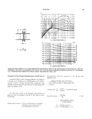
Figure 2-18. Flow coefficient "C" for square edged orifices. By permission, Crane Co. [3], Technical Paper 410 Engineering Div. (1976) and
Fluid Meters, Their Theory and Application Part 1, 6th Ed., 1971, American Society of Mechanical Engineers and, Tuve, G. L. and Sprenkle,
R. E., "Orifice Discharge Coefficients for Viscous Liquids," Instruments Nov. 1933, p. 201.
Example 2-1: Pipe Sizing Using Resistance Coefficients, K Estimated flow velocity for assumed 2 in. Sch. 40 pipe (See
Appendix A-16)
A plant decides to add a nitrogen blanket (at 5 psig) to
a storage tank holding up to 25,000 gallons of a hydro- (20 gpm) (8. 33 lb I gal) (0. 81 SpGr)
carbon mixture having kerosene-like properties and (62.3X0.81) (3.355in 2) (60sec/min)/l44
pumps this material into a process reactor operating at 30 = l. 91 ft/sec
psig. (See Figure 2-19)
v2 (l.91) 2
Velocity head 0. 05664 ft of fluid
2g 2(32.2)
The flow rate needs to be 20 gpm. Connections of
pipe and valve are flanged, with the 6°---90° elbows added 50.6 Qp
in the line. Reynolds number dµ (2- 49)
50.6 (20)(0.81 X 62.3)
(2.06)(1.125 cp)
Pump suction velocity= 2 ft/sec (Selected low in accordance
with good pump suction practice, Re= 22,036 (turbulent)
from Table 2-4 or Table 2-7). e/ D = 0. 00088, Figure 2 - l 1