
Page 137 - REPOWER REFERENCE GUIDE (2020)
P. 137
Ignition System
Inspection
1. Inspect each spark plug for the manufacturer and spark plug number. All plugs must be from the same manufacturer and
have the same spark plug number.
2. Inspect each plug for worn electrodes and for glazed, broken, or blistered porcelain. Check the joint between the insulator
and the shell for cracks. Replace as necessary.
Installation
1. Clean the cylinder head spark plug seat.
2. Adjust the spark plug gap with the appropriately sized, round‑tipped feeler gauge.
IMPORTANT: In the absence of a torque wrench or if limited access prevents the use of a torque wrench, hand‑tighten the
spark plugs until they seat in the cylinder head and then securely tighten with the appropriate ratchet and socket.
3. Install the spark plugs and tighten to the specified torque.
Description Nm lb‑in. lb‑ft
Spark plugs (new cylinder head) 30 – 22.1
Spark plugs (used cylinder head) 14 123.9 –
4. Install the spark plug wires in the proper order. Refer to Spark Plug Wire Inspection and Installation.
Spark Plug Wire Inspection and Installation
Inspection
NOTE: Use care when removing the spark plug wires and the boots from the spark plugs. Twist the boot 1/2 turn before
removing. Firmly grasp and pull on the boot to remove the wire.
1. Visually inspect the spark plug wires and the coil wire for damage.
2. Visually inspect the spark plug boots for damage.
3. Check the spark plug wires and the coil wire for continuity using a multimeter.
4. Replace any damaged wires.
Installation
IMPORTANT: Only use spark plug wires recommended for marine applications.
1. Disconnect each spark plug wire as it is to be replaced.
NOTE: Replace one spark plug wire at a time to reduce the risk of routing error.
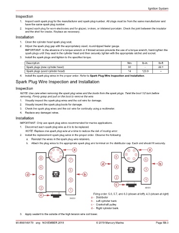
2. Install the replacement spark plug wires in the proper order. Observe the following:
a. Reinstall the wires in the spark plug wire retainers.
b. Attach the plug wires to the appropriate spark plug and terminal on the distributor cap. Each end should fit securely.
3 6 a 5 4 a
4 5 6 3
8 8 7 6 1 2
1 2 7 5
d b
6 4
5 3
d b
4 2
3 1
c
2 48681
1
c Firing order: 5.0, 5.7, and 6.3 (shown at left); 4.3 (shown at right)
29222 a - Distributor
b - Left cylinder bank
c - Crankshaft pulley
d - Right cylinder bank
3. Apply sealant to the outside of the high tension wire coil tower.
90-8M0149179 eng NOVEMBER 2018 © 2019 Mercury Marine Page 5B-3