
Page 140 - REPOWER REFERENCE GUIDE (2020)
P. 140
Ignition System
After 30–100 engine hours, the tolerance between the distributor (high‑voltage switch) and the drive components may increase.
As the timing chain, timing gears, distributor shaft drive gear, and cam gear all wear in, the rotor shaft may become slightly out
of phase with the distributor housing, which can result in misfire under load.
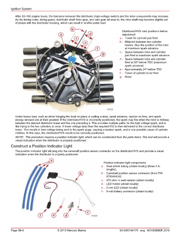
b Distributor/HVS rotor positions before
a d adjustment
c a - Tower for cylinder just fired
e b - Midpoint between two cylinder
towers. Also the position of the rotor
f at maximum spark advance.
g c - Space between rotor and cylinder
just fired at maximum spark advance
d - Space between rotor and cylinder
fired at 30º before TDC (maximum
spark advance)
e - Approximately 24º before TDC
f - Tower of cylinder to be fired
g - Rotor
54232
Under heavy load, such as when bringing the boat on plane or pulling a skier, spark advance, injector on time, and spark
energy demand are at their greatest. If the distributor/HVS is incorrectly positioned, the spark may fire when the rotor is midway
between the desired distributor tower and the one preceding it. This provides multiple paths for the high voltage spark, and is
like trying to fire two cylinders at once. A lower voltage (less than the required KV) is then delivered to the correct distributor
tower. This results in less voltage being sent to the spark plugs, causing a weaker spark, and is one possible cause of cylinder
misfires. In this case, the distributor/HVS needs to be correctly positioned.
NOTE: This procedure requires a position indicator light, which can be constructed from the parts listed. This tool will provide a
visual indication when the distributor is properly positioned.
Construct a Position Indicator Light
The position indicator light will plug into the camshaft position sensor connector on the distributor/HVS and provide a visual
indication when the distributor is properly positioned.
a
Position indicator light components
a - Heat shrink tubing (obtain locally) (three 3 in.
lengths)
b b - Camshaft position sensor connector (from P/N
879346A34)
c - 470 ohm ¼ watt resistor (obtain locally)
d - LED holder (obtain locally)
e - 5 mm LED (obtain locally)
f - 9‑volt battery connector (obtain locally)
c
f e d 54525
Page 5B-6 © 2019 Mercury Marine 90-8M0149179 eng NOVEMBER 2018