
Page 141 - REPOWER REFERENCE GUIDE (2020)
P. 141
Ignition System
Also required: 9‑volt battery (obtain locally)
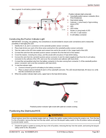
a b c Position indicator light schematic
a - Camshaft position sensor connector (from
P/N 879346A34)
d
A b - Heat shrink tubing
B c - Cathode (–) (short lead) of light emitting
C
diode (LED)
e d - LED
h e - LED holder
b g f
54336
f - Anode (+) (long lead) of LED
g - 470 ohm ¼ watt resistor
h - 9‑volt battery connector
Constructing the Position Indicator Light
IMPORTANT: Crimping, not soldering, the connections is recommended to ensure solid connections and to reduce the
possibility of damaging the LED.
1. Identify the A, B, and C connectors on the camshaft position sensor connector.
2. Place heat shrink over each of the three wires coming from the camshaft position sensor connector.
3. Trim the leads on the 470 ohm resistor and connect one end to the anode (+) (the longer lead) of the LED.
4. Connect the wire from the camshaft position sensor connector B to the free end of the resistor.
5. Cover the resistor, including the crimps, and the anode with one piece of heat shrink tubing.
6. Connect the wire from the camshaft position sensor connector A and the black (negative) lead from the 9‑volt battery
connector to the cathode of the LED, and cover the connection and cathode with heat shrink.
7. Connect the red (positive) wire from the battery connector to the wire coming from connector C of the camshaft position
sensor connector, and cover the connection with heat shrink.
8. To test the indicator light,
a. Connect a known good 9‑volt battery to the battery connector.
b. Place a jumper across terminals B and C of the camshaft connector. The LED should illuminate. If it does not, verify
that the connections are secure.
9. When the position indicator light works, apply heat to the heat shrink tubing.
54339
Finished position indicator light shown with optional conduit covering
Positioning the Distributor/HVS
! WARNING
Avoid serious injury from accidental engine start up. Disable the ignition system before turning the engine over. Turn the key
to the off position, remove the key from the key switch, and turn the lanyard safety switch to the off position before activating
a remote starter switch.
1. Disable the ignition system by turning the key to the off position, removing the key from the switch, and turning the lanyard
safety switch to the off position.
90-8M0149179 eng NOVEMBER 2018 © 2019 Mercury Marine Page 5B-7