
Page 105 - Installation Manual - GenII DTS
P. 105
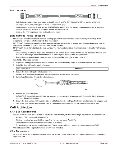
14-Pin Data Harness

            Low Loss - Gray


                                                                                                         70753
               •  Only 8 pins are wired ‑ there is no wiring for CAN P (pins G and F), CAN H (pins E and P), or trim (pins H and J)
               •  Power (red, black, and purple; pins A, B and C) wires are 10 gauge
               •  Cable has gray sheathing; a label reading "ENGINE NO CAN P/H" is at the end with the male connector, while a label
                  reading "HELM NO CAN P/H" is at the end with the female connector.
               •  Used on the inner engines on triple and quad‑engine boats
            Data Harness Pulling Procedure

               IMPORTANT: Do not route the data harness near high‑power VHF coax or radios. Electrical fields generated by these
               components could cause interference with data transmission.
               IMPORTANT: Do not route the data harness near sharp edges, hot surfaces, or moving parts. Fasten cables away from any
               sharp edges, fasteners, or objects that could wear into the harness.
               IMPORTANT: Avoid sharp bends in the data harness. The minimum bend radius should be 7.6 cm (3.0 in.) for the final wiring
               installation.
               •  Daisy‑chaining or linking of 14‑pin data harnesses is not allowed. Each harness must make the required distance in one
                  run, due to the voltage drop in each connection. If more length is needed, order a longer harness.
               •  Ensure that the harness length exceeds the service length of the routing by at least 18 cm (6 in.).
               To install the 14‑pin data harness:
               1.  Inspect the routing path to ensure that the surfaces are free of any sharp edges or burrs that could cut the harness.
               2.  Install the data cable puller onto the harness.
                   Data Cable Puller                                             888462A 1

               3.  Secure the data cable puller with two cable ties.
                  IMPORTANT: The cable ties must be tight to prevent any slipping during installation.
               4.  Carefully pull the cable through the selected route.


                                                                                           3836
               5.  Remove the data cable puller.
                  IMPORTANT: Carefully inspect the data harness pins to ensure that all pins are securely fastened to the data harness
                  connector following installation.
               6.  Secure the data harness with mounting clips or cable ties along the routing path where it is not contained in a rigging tube.
               7.  Secure the data harness with mounting clips or cable ties within 25 cm (10 in.) of the connections at either end.
            CAN Architecture
            CAN Bus Requirements

               To avoid communication issues that could result in the loss of control, strict CAN bus length requirements must be followed:
               •  Maximum CAN bus length is 70 m (230 ft).
               •  Maximum length of any one CAN bus drop off of the main harness is 7 m (23 ft).
               •  Combined length of all drops should not exceed 36 m (118 ft).
               •  For applications that require lengths in excess of these, contact a Mercury product applications engineer (PAE).
               All CAN buses must be properly terminated at both ends of the bus.
            CAN Terminators
               Each CAN bus has two terminators installed, one at each of the furthest ends of the bus. There are two styles of terminators:
               10‑pin and 2‑pin.


            90-8M0161677 eng MARCH 2021                          © 2021 Mercury Marine                      Page 3D-3