
Page 108 - Installation Manual - GenII DTS
P. 108
Accessories
Lubricant, Sealant, Adhesives
Tube Ref No. Description Where Used Part No.
25 Liquid Neoprene Electrical connections 92- 25711 3
Accessory Power/Relay Harness Kits
Accessory Relay Harness Installation Options
These instructions cover two options for installing an accessory relay harness with a 3‑pin connector or an accessory relay
harness with a 10‑pin connector.
• The 3‑pin accessory relay harness connects directly to the helm harness. The 3‑pin relay will turn on when a 4‑position key
switch is turned to the ACC position.
• The 10‑pin accessory relay harness connects to the junction box. The 10‑pin relay will turn on when a 3 or 4‑position key
switch is turned to the ON position.
Installing the 3‑Pin Accessory Relay Harness to the Helm Harness
1. Connect the relay harness to the helm harness.
a b a - Relay harness connector
b - Helm harness connector
72417
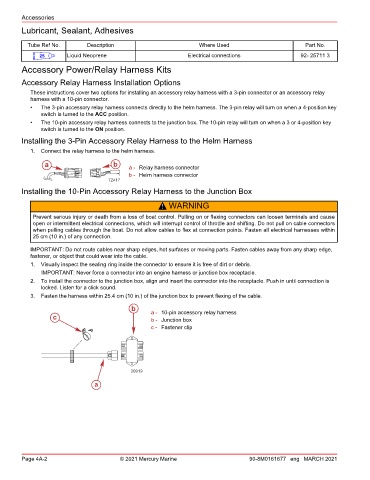
Installing the 10‑Pin Accessory Relay Harness to the Junction Box
! WARNING
Prevent serious injury or death from a loss of boat control. Pulling on or flexing connectors can loosen terminals and cause
open or intermittent electrical connections, which will interrupt control of throttle and shifting. Do not pull on cable connectors
when pulling cables through the boat. Do not allow cables to flex at connection points. Fasten all electrical harnesses within
25 cm (10 in.) of any connection.
IMPORTANT: Do not route cables near sharp edges, hot surfaces or moving parts. Fasten cables away from any sharp edge,
fastener, or object that could wear into the cable.
1. Visually inspect the sealing ring inside the connector to ensure it is free of dirt or debris.
IMPORTANT: Never force a connector into an engine harness or junction box receptacle.
2. To install the connector to the junction box, align and insert the connector into the receptacle. Push in until connection is
locked. Listen for a click sound.
3. Fasten the harness within 25.4 cm (10 in.) of the junction box to prevent flexing of the cable.
b a - 10‑pin accessory relay harness
c b - Junction box
c - Fastener clip
20919
a
Page 4A-2 © 2021 Mercury Marine 90-8M0161677 eng MARCH 2021