
Page 106 - Installation Manual - GenII DTS
P. 106
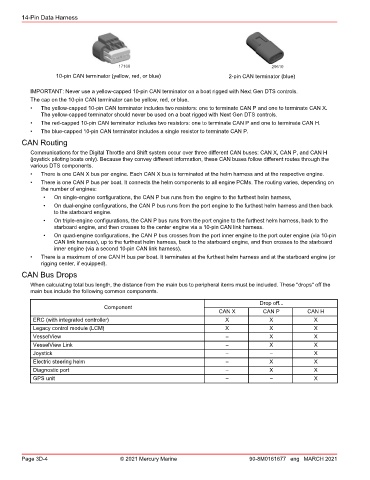
14-Pin Data Harness


                                        17168                                              29610
                    10-pin CAN terminator (yellow, red, or blue)             2-pin CAN terminator (blue)

           IMPORTANT: Never use a yellow‑capped 10‑pin CAN terminator on a boat rigged with Next Gen DTS controls.
           The cap on the 10‑pin CAN terminator can be yellow, red, or blue.
           •   The yellow‑capped 10‑pin CAN terminator includes two resistors: one to terminate CAN P and one to terminate CAN X.
               The yellow‑capped terminator should never be used on a boat rigged with Next Gen DTS controls.
           •   The red‑capped 10‑pin CAN terminator includes two resistors: one to terminate CAN P and one to terminate CAN H.
           •   The blue‑capped 10‑pin CAN terminator includes a single resistor to terminate CAN P.
        CAN Routing

           Communications for the Digital Throttle and Shift system occur over three different CAN buses: CAN X, CAN P, and CAN H
           (joystick piloting boats only). Because they convey different information, these CAN buses follow different routes through the
           various DTS components.
           •   There is one CAN X bus per engine. Each CAN X bus is terminated at the helm harness and at the respective engine.
           •   There is one CAN P bus per boat. It connects the helm components to all engine PCMs. The routing varies, depending on
               the number of engines:
               •   On single‑engine configurations, the CAN P bus runs from the engine to the furthest helm harness,
               •   On dual‑engine configurations, the CAN P bus runs from the port engine to the furthest helm harness and then back
                   to the starboard engine.
               •   On triple‑engine configurations, the CAN P bus runs from the port engine to the furthest helm harness, back to the
                   starboard engine, and then crosses to the center engine via a 10‑pin CAN link harness.
               •   On quad‑engine configurations, the CAN P bus crosses from the port inner engine to the port outer engine (via 10‑pin
                   CAN link harness), up to the furthest helm harness, back to the starboard engine, and then crosses to the starboard
                   inner engine (via a second 10‑pin CAN link harness).
           •   There is a maximum of one CAN H bus per boat. It terminates at the furthest helm harness and at the starboard engine (or
               rigging center, if equipped).
        CAN Bus Drops
           When calculating total bus length, the distance from the main bus to peripheral items must be included. These "drops" off the
           main bus include the following common components.

                                                                                       Drop off...
                                   Component
                                                                         CAN X          CAN P          CAN H
            ERC (with integrated controller)                                X             X              X
            Legacy control module (LCM)                                     X             X              X
            VesselView                                                      –             X              X
            VesselView Link                                                 –             X              X
            Joystick                                                        –             –              X
            Electric steering helm                                          –             X              X
            Diagnostic port                                                 –             X              X
            GPS unit                                                        –             –              X


        Page 3D-4                        © 2021 Mercury Marine                      90-8M0161677 eng MARCH 2021