
Page 111 - Installation Manual - GenII DTS
P. 111
Accessories
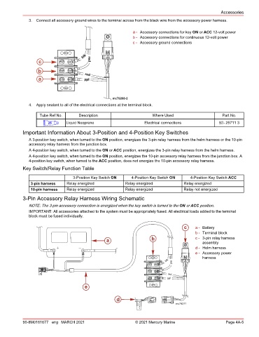
3. Connect all accessory ground wires to the terminal across from the black wire from the accessory power harness.
a - Accessory connections for key ON or ACC 12‑volt power
b - Accessory connections for continuous 12‑volt power
c - Accessory ground connections
blk
c red
b
red
a ppl
mc79268-2
4. Apply sealant to all of the electrical connections at the terminal block.
Tube Ref No. Description Where Used Part No.
25 Liquid Neoprene Electrical connections 92- 25711 3
Important Information About 3‑Position and 4‑Position Key Switches
A 3‑position key switch, when turned to the ON position, energizes the 3‑pin relay harness from the helm harness or the 10‑pin
accessory relay harness from the junction box.
A 4‑position key switch, when turned to the ON or ACC position, energizes the 3‑pin relay harness from the helm harness.
A 4‑position key switch, when turned to the ON position, energizes the 10‑pin accessory relay harness from the junction box. A
4‑position key switch, when turned to the ACC position, does not energize the 10‑pin accessory relay harness.
Key Switch/Relay Function Table
3‑Position Key Switch ON 4‑Position Key Switch ON 4‑Position Key Switch ACC
3‑pin harness Relay energized Relay energized Relay energized
10‑pin harness Relay energized Relay energized Relay not energized
3‑Pin Accessory Relay Harness Wiring Schematic
NOTE: The 3‑pin accessory connection is energized when the key switch is turned to the ON or ACC position.
IMPORTANT: All accessories attached to the system must be appropriately fused. All electrical loads added to the terminal
block must be fused individually.
c a - Battery
b - Terminal block
a b c - 3‑pin relay harness
assembly
d - Helm harness
e - Accessory power
harness
blk red
red
ppl
e
d
mc79271
LOAD
SWI TCHED
90-8M0161677 eng MARCH 2021 © 2021 Mercury Marine Page 4A-5