
Page 157 - Installation Manual - GenII DTS
P. 157
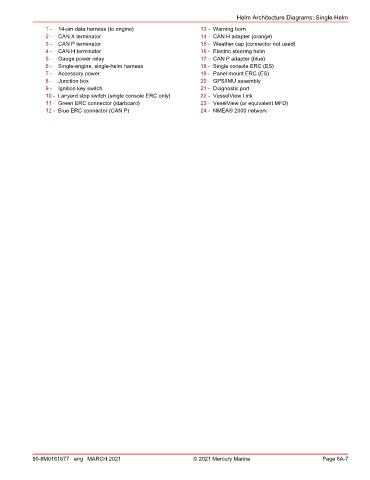
Helm Architecture Diagrams: Single Helm
                1 -  14‑pin data harness (to engine)               13 - Warning horn
                2 -  CAN X terminator                              14 - CAN H adapter (orange)
                3 -  CAN P terminator                              15 - Weather cap (connector not used)
                4 -  CAN H terminator                              16 - Electric steering helm
                5 -  Gauge power relay                             17 - CAN P adapter (blue)
                6 -  Single‑engine, single‑helm harness            18 - Single console ERC (ES)
                7 -  Accessory power                               19 - Panel mount ERC (ES)
                8 -  Junction box                                  20 - GPS/IMU assembly
                9 -  Ignition key switch                           21 - Diagnostic port
                10 - Lanyard stop switch (single console ERC only)  22 - VesselView Link
                11 - Green ERC connector (starboard)               23 - VeselView (or equivalent MFD)
                12 - Blue ERC connector (CAN P)                    24 - NMEA® 2000 network


            90-8M0161677 eng MARCH 2021                          © 2021 Mercury Marine                      Page 6A-7