
Page 161 - Installation Manual - GenII DTS
P. 161
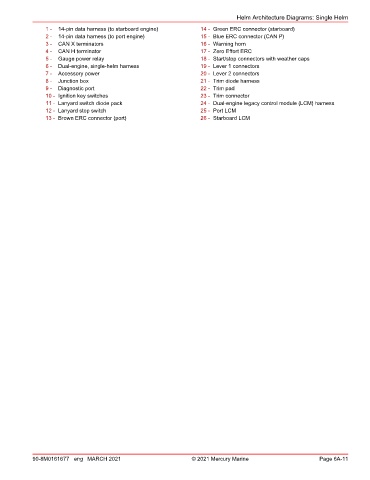
Helm Architecture Diagrams: Single Helm
                1 -  14‑pin data harness (to starboard engine)     14 - Green ERC connector (starboard)
                2 -  14‑pin data harness (to port engine)          15 - Blue ERC connector (CAN P)
                3 -  CAN X terminators                             16 - Warning horn
                4 -  CAN H terminator                              17 - Zero Effort ERC
                5 -  Gauge power relay                             18 - Start/stop connectors with weather caps
                6 -  Dual‑engine, single‑helm harness              19 - Lever 1 connectors
                7 -  Accessory power                               20 - Lever 2 connectors
                8 -  Junction box                                  21 - Trim diode harness
                9 -  Diagnostic port                               22 - Trim pad
                10 - Ignition key switches                         23 - Trim connector
                11 - Lanyard switch diode pack                     24 - Dual‑engine legacy control module (LCM) harness
                12 - Lanyard stop switch                           25 - Port LCM
                13 - Brown ERC connector (port)                    26 - Starboard LCM


            90-8M0161677 eng MARCH 2021                         © 2021 Mercury Marine                      Page 6A-11