
Page 234 - Toro Irrigation Product Catalogue August 2020
P. 234
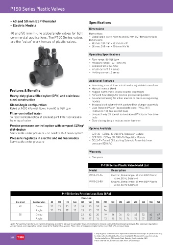
P150 Series Plastic Valves


        • 40 and 50 mm BSP (Female)                           Specifications
        • Electric Models
                                                              Dimensions
        40 and 50 mm in-line globe/angle valves for light     Body styles:
        commercial applications. The P150 Series valves       •  Globe/angle valve: 40 mm and 50 mm BSP female threads
        are the “value” work horses of plastic valves.        Dimensions:
                                                              •  40 mm: 184 mm x 92 mm H x W
                                                              •  50 mm: 241 mm x 156 mm H x W


                                                              Operating Specifications
                                                              •  Flow range: 80-568 Lpm
                                                              •  Pressure range: 140-1000 kPa
                                                              •  Solenoid: 50Hz (24 VAC)
                                                              •  Inrush current: 0.4 amps
                                                              •  Holding current: .2 amps


                                                              Additional Features
                                                              •  Non-rising, manual flow control handle; adjustable to zero flow
                                                              •  Manual internal bleed
        Features & Benefits                                   •  Rugged Santoprene, double beaded diaphragm
        Heavy-duty glass-filled nylon (GFN) and stainless-    •  Forward flow design for precise pressure regulation
        steel construction                                    •  No external tubing for either electric or pressure regulating
                                                                models
        Globe/Angle configuration                             •  Encapsulated solenoid with captured hex plunger assembly
        Rated at 1000 kPa with flows from 80 to 568 Lpm       •  Lilac Recycled Water Tag available (code: RWSG-KIT)
                                                              •  Positive O-ring seal on inlet plug
        Filter-controlled Water                               •  Unique 3-way SS bonnet screws accept Phillips or hex driver
        To resist contamination of solenoid port. Filter serviceable   tools
        from top of valve.                                    •  Slow closing design reduces water hammer
        Precise pressure control option with compact EZReg®
        dial-design                                            Options Available
        Serviceable under pressure – no need to shut down system  •  EZR-30 - EZReg, 30-200 kPa Regulator Module
        Pressure regulates in electric and manual modes       •  EZR-100 - EZReg, 30-700 kPa Regulator Module
        Serviceable under pressure                            •  DCLS-P - Potted DC Latching Solenoid Assembly (max.
                                                                pressure 820 kPa)

                                                               Warranty

                                                              •  Five years

                                                                       P-150 Series Plastic Valve Model List
                                                               Model          Description

                                                               P150-23-56     Electric, Globe/Angle, 40 mm BSP Plastic
                                                                               Valve, 50 Hz Solenoid
                                                               P150-23-58     Electric, Globe/Angle, 50 mm BSP Plastic
                                                                               Valve, 50 Hz Solenoid

                                            P-150 Series Friction Loss Data (kPa)
                                                         Flow – Lpm
            Size (mm)   Configuration  80  100  120  140  160  180  200  250  300  350  400  450   500  550  568
              40          Globe     22   21   21    17   18   20   31    46
                          Angle     21   21   22    15   13   13   19    26
              50          Globe                          22   22   20    19   26   34   42    42   52   62   67
                          Angle                          18   17   14    13   16   24   24    26   32   37   39

        Note: For optimum performance when designing a system, be sure to calculate total friction loss to ensure sufficient downstream pressure. For optimum regulation
        performance, size regulating valves toward the higher flow ranges. Flow rates are recommended not to exceed 35 kPa pressure loss.

                                                                  Company policy is one of constant improvement and therefore changes in specifications may
        218                                                       be made without notice and without incurring liability. Please refer to www.toro.com.au
                                                                  Toro Australia Pty Ltd, 53 Howards Road, Beverley, South Australia, 5009.
                                                                  Phone 1300 130 898, fax (08) 8243 2488. A.B.N. 47 001 310 443