
Page 125 - I:\Irrigation\Golf\
P. 125
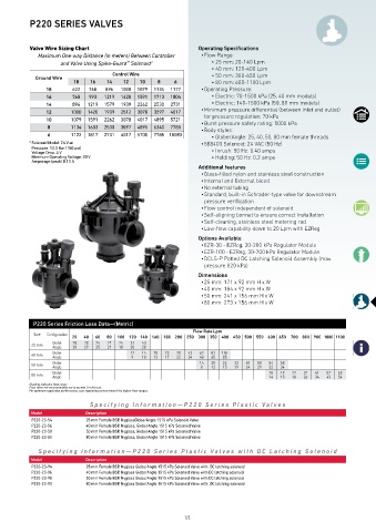
P220 SERIES VALVES


          Valve Wire Sizing Chart                               Operating Specifications
             Maximum One-way Distance (in meters) Between Controller    • Flow Range:
                    and Valve Using Spike-Guard  Solenoid*          • 25 mm: 20-140 Lpm
                                         ™
                                                                    • 40 mm: 120-400 Lpm
                                     Control Wire                   • 50 mm: 300-650 Lpm
            Ground Wire
                        18    16   14   12   10    8    6           • 80 mm: 600-1100 Lpm
                18      622  768  896  1000  1079  1134  1177    • Operating Pressure:
                16      768  993  1219  1420  1591  1713  1804      • Electric: 70-1500 kPa (25, 40 mm models)
                14      896  1219  1579  1939  2262  2530  2731     • Electric: 140-1500 kPa (50, 80 mm models)
                12      1000  1420  1939  2512  3078  3597  4017  • Minimum pressure differential (between inlet and outlet)
                                                                  for pressure regulation: 70 kPa
                10      1079  1591  2262  3078  4017  4895  5721  • Burst pressure safety rating: 5000 kPa
                8       1134  1603  2530  3597  4895  6340  7785  • Body styles:
                6       1122  1817  2731  4017  5700  7785 10083     • Globe/Angle: 25, 40, 50, 80 mm female threads
          *  Solenoid Model: 24 V ac                             • 588403 Solenoid: 24 VAC (50 Hz)
           Pressure: 10,3 Bar (150 psi)
           Voltage Drop: 4 V                                        • Inrush: 50 Hz: 0.40 amps
           Minimum Operating Voltage: 20 V                          • Holding: 50 Hz: 0.2 amps
           Amperage (peak) 0.12 A
                                                                Additional features
                                                                 • Glass-filled nylon and stainless steel construction
                                                                 • Internal and External bleed
                                                                 • No external tubing
                                                                 • Standard, built-in Schrader-type valve for downstream
                                                                  pressure verification
                                                                 • Flow control independent of solenoid
                                                                 • Self-aligning bonnet to ensure correct installation
                                                                 • Self-cleaning, stainless steel metering rod
                                                                 • Low-flow capability down to 20 Lpm with EZReg
                                                                Options Available
                                                                 • EZR-30 - EZReg, 30-200 kPa Regulator Module
                                                                 • EZR-100 - EZReg, 30-700 kPa Regulator Module
                                                                 • DCLS-P Potted DC Latching Solenoid Assembly (max.
                                                                  pressure 820 kPa)
                                                                Dimensions
                                                                 • 25 mm: 171 x 92 mm H x W
                                                                 • 40 mm: 184 x 92 mm H x W
                                                                 • 50 mm: 241 x 156 mm H x W
                                                                 • 80 mm: 273 x 156 mm H x W


            P220 Series Friction Loss Data—(Metric)
                                                              Flow Rate Lpm
            Size
                        20  40  60  80  100 120 140  160 180 200  250 300 350  400 450 500  550 600 650  700 800 900 1000 1100
           25 mm  Globe  28  28  24  22  24  31  43
                                              28
                                          20
                                       18
                            29
                        28
                  Angle
                               25
                                   21
                  Globe                   12  14  18  23  28  43  62  81  104
           40 mm  Angle                    9  10  13  17  22  34  48  65  85
           50 mm  Globe                                         14  20  26  33  40  50  54  58
                                                                               24
                                                                           19
                                                                    12
                                                                        15
                                                                                   29
                  Angle
                                                                                          34
                                                                                      32
                                                                 8
           80 mm  Globe                                                               18  19  22  32  41  52  65
                  Angle                                                               14  15  18  26  34  43  54
          Shading indicates flow range.
          Flow rates are recommended not to exceed 35 kPa loss.
          For optimum regulation performance, size regulating valves toward the higher flow ranges.
                             Specifying Information—P220 Series Plastic  V alves
           Model            Description
           P220-23-54       25 mm Female BSP, NyglassGlobe/Angle 1515 kPa Solenoid Valve
           P220-23-56       40 mm Female BSP, Nyglass, Globe/Angle 1515 kPa Solenoid Valve
           P220-23-58       50 mm Female BSP, Nyglass, Globe/Angle 1515 kPa Solenoid Valve
           P220-23-50       80 mm Female BSP, Nyglass, Globe/Angle 1515 kPa Solenoid Valve
             Specifying Information—P220 Series Plastic  V alves with DC Latching Solenoid
           Model            Description
           P220-23-94       25 mm Female BSP, Nyglass Globe/Angle 1515 kPa Solenoid Valve with  DC latching solenoid
           P220-23-96       40 mm Female BSP, Nyglass Globe/Angle 1515 kPa Solenoid Valve with DC latching solenoid
           P220-23-98       50 mm Female BSP, Nyglass Globe/Angle 1515 kPa Solenoid Valve with DC latching solenoid
           P220-23-90       80 mm Female BSP, Nyglass Globe/Angle 1515 kPa Solenoid Valve with  DC latching solenoid
                                                           123