Page 206 - Physics Form 5 KSSM_Neat
P. 206

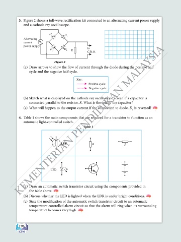
3.  Figure 2 shows a full-wave rectification kit connected to an alternating current power supply
               and a cathode ray oscilloscope.


                               D
                                4       D
                                         1
               Alternating
               current
            KEMENTERIAN PENDIDIKAN MALAYSIA
               power supply
                               D       D             to
                                3        2  R
                                                     C.R.O.

                                 Figure 2
               (a)  draw arrows to show the flow of current through the diode during the positive half
                  cycle and the negative half cycle.
                         D          D
                          4          1
                                               Key:
                                                      Positive cycle
                                                      Negative cycle

                         D         D
               (b) Sketch what is displayed on the cathode ray oscilloscope screen if a capacitor is
                                     3
                          2
                  connected parallel to the resistor, R. What is the role of the capacitor?
               (c)  What will happen to the output current if the connection to diode, D  is reversed?
                                                                                1
                                                                                      LED
             4.  Table 1 shows the main components that are required for a transistor to function as an
                                                          LDR
               automatic light-controlled switch.                                           LED
                                                   Table 1       LDR

                                                                     S
                                                                 LED
                                      LDR               R                  S
                                                    LED
                        LDR                                    R
                                                S


                               LED
                                   S R

                      R
               (a)  draw an automatic switch transistor circuit using the components provided in
                  the table above.
               (b) Discuss whether the LED is lighted when the LDR is under bright conditions.
               (c)  State the modification of the automatic switch transistor circuit to an automatic
                  temperature-controlled alarm circuit so that the alarm will ring when its surrounding
                  temperature becomes very high.


            196
   201   202   203   204   205   206   207   208   209   210   211