
Page 207 - Physics Form 5 KSSM_Neat
P. 207
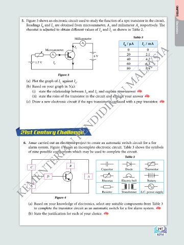
5.  Figure 3 shows an electronic circuit used to study the function of a npn transistor in the circuit.   CHAPTER 5
                Readings I  and I  are obtained from microammeter, A  and miliameter A  respectively. The
                          B
                                                                 1
                                                                                  2
                                C
                rheostat is adjusted to obtain different values of I  and I  as shown in Table 2.        Electronics
                                                            B     C
                                                                               Table 2
                                             Milliammeter
                                                 A                       I  / μA    I  / mA
               KEMENTERIAN PENDIDIKAN MALAYSIA
                                                  2                       B          C
                                             I
                            Microammeter     C                              0          0
                               A                                           20          2.1
                                 1                      6 V
                                                                           40          4.2
                      1.5 V     I
                                 B                                         60          6.3
                                                                           80          8.4

                                   Figure 3
                (a)  Plot the graph of I  against I .
                                    C        B
                (b) Based on your graph in 5(a):
                    (i)  state the relationship between I  and I  and explain your answer
                                                    B
                                                          C
                    (ii)  state the roles of the transistor in the circuit and explain your answer
                (c)  draw a new electronic circuit if the npn transistor is replaced with a pnp transistor.


             21st Century Challenge


                6.  Amar carried out an electronic project to create an automatic switch circuit for a fire
                  alarm system. Figure 4 shows an incomplete electronic circuit. Table 3 shows the symbols
                  of nine possible components which may be used to complete the circuit.
                                                                          Table 3

                                          B
                   C
                                                            Capasitor      Diode      Thermistor
                             D                       A
                                                             Rheostat   Electric bell  Battery
                   E
                                                             Resistor   Transformer  A.C. power supply
                                 Figure 4
                  (a)  Based on your knowledge of electronics, select any suitable components from Table 3
                     to complete the transistor circuit as an automatic switch for a fire alarm system.
                  (b) State the justification for each of your choice.


                                                                                              197