
Page 485 - Cardiac Nursing
P. 485
009
9/2
9/0
10.
qxd
8:2
g
ara
Apt
61
e 4
0
61
10.
K34
K34
0-c
LWB K34 0-c 21_ p46 0-5 10. qxd 0 9/0 9/2 009 0 0 8:2 8 A M P a a g e 4 61 Apt ara
L L LWB
LWBK340-c21_21_p460-510.qxd 09/09/2009 08:28 AM Page 461 Aptara
21_
8 A
p46
0-5
P
P
M
C HAPTER 2 1 / Hemodynamic Monitoring 461
n
ng
di
A Ascending
s
ce
Aorta R. Pulmonary
Artery y
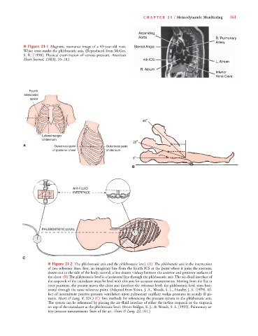
■ Figure 21-1 Magnetic resonance image of a 43-year-old man. Sternal Angle
White cross marks the phlebostatic axis. (Reproduced from McGee,
S. R. [1998]. Physical examination of venous pressure. American
Heart Journal, 136[1], 10–18.) 4th ICS
6
6
L. Atrium
R . At r i
R A ium
Inferior
Vena Cava
■ Figure 21-2 The phlebostatic axis and the phlebostatic level. (A) The phlebostatic axis is the intersection
of two reference lines: first, an imaginary line from the fourth ICS at the point where it joins the sternum,
drawn out to the side of the body; second, a line drawn midway between the anterior and posterior surfaces of
the chest. (B) The phlebostatic level is a horizontal line through the phlebostatic axis. The air–fluid interface of
the stopcock of the transducer must be level with this axis for accurate measurements. Moving from the flat to
erect positions, the patient moves the chest and therefore the reference level; the phlebostatic level stays hori-
zontal through the same reference point. (Adapted from Shinn, J. A., Woods, S. L., Huseby, J. S. [1979]. Ef-
fect of intermittent positive pressure ventilation upon pulmonary capillary wedge pressures in acutely ill pa-
tients. Heart & Lung, 8, 324.) (C) Two methods for referencing the pressure system to the phlebostatic axis.
The system can be referenced by placing the air–fluid interface of either the in-line stopcock or the stopcock
on top of the transducer at the phlebostatic level. (From Bridges, E. J., & Woods, S. L. [1993]. Pulmonary ar-
tery pressure measurement: State of the art. Heart & Lung, 22, 101.)