
Page 687 - Cardiac Nursing
P. 687
7
/1/
09
qxd
p65
5-7
04.
663
Ap
tar
g
49
AM
P
28_
LWBK340-c28_p655-704.qxd 7/1/09 9:9:49 AM Page 663 Aptara
L L LWB K34 0-c 28_ p65 5-7 04. qxd 7 /1/ 09 9: 49 AM P a a g e e 663 Ap tar a a
LWB
K34
0-c
C HAPTER 2 8 / Pacemakers and Implantable Defibrillators 663
generator through the pacing lead to the myocardium, through the only way to alter its pacing parameters is with a program-
the myocardium, and back to the pulse generator, thus complet- mer that communicates with the pacemaker through a wand
ing the circuit. 23,24 placed over the pulse generator. A temporary pulse generator is
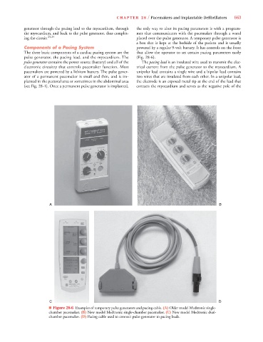
a box that is kept at the bedside of the patient and is usually
Components of a Pacing System powered by a regular 9-volt battery. It has controls on the front
The three basic components of a cardiac pacing system are the that allow the operator to set certain pacing parameters easily
pulse generator, the pacing lead, and the myocardium. The (Fig. 28-6).
pulse generator contains the power source (battery) and all of the The pacing lead is an insulated wire used to transmit the elec-
electronic circuitry that controls pacemaker function. Most trical current from the pulse generator to the myocardium. A
pacemakers are powered by a lithium battery. The pulse gener- unipolar lead contains a single wire and a bipolar lead contains
ator of a permanent pacemaker is small and thin, and is im- two wires that are insulated from each other. In a unipolar lead,
planted in the pectoral area or sometimes in the abdominal area the electrode is an exposed metal tip at the end of the lead that
(see Fig. 28-1). Once a permanent pulse generator is implanted, contacts the myocardium and serves as the negative pole of the
A B
C D
■ Figure 28-6 Examples of temporary pulse generators and pacing cable. (A) Older model Medtronic single-
chamber pacemaker. (B) New model Medtronic single-chamber pacemaker. (C) New model Medtronic dual-
chamber pacemaker. (D) Pacing cable used to connect pulse generator to pacing leads.