
Page 688 - Cardiac Nursing
P. 688
92806_c28.qxd 11/21/11 11:00 AM Page 664
664 P A R T I V / Pathophysiology and Management Disease
Figure 28-7 Pacing leads. (A) Passive fixation lead with tines on
the end to hold lead in position. (B) Active fixation screw lead; top
shows screw retracted, bottom shows screw extended.
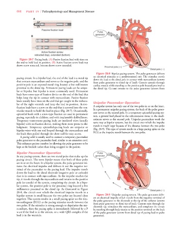
Figure 28-8 Bipolar pacing system. The pulse generator delivers
an electrical stimulus at a predetermined rate. The stimulus trave l s
pacing circuit. In a bipolar lead, the end of the lead is a metal tip down the lead to the distal pole in contact with myocardium (arrows
that contacts myocardium and serves as the negative pole, and the
from pulse generator to distal tip of lead). Current spreads through
p o s i t i ve pole is an exposed metal ring located a few millimeters cardiac muscle while traveling to the positive pole located proximal to
proximal to the distal tip. Permanent pacing leads can be unipo- the distal tip. Cu r rent returns to the pulse generator (arrows fro m
lar or bipolar, but bipolar is more commonly used. Pe r m a n e n t
leads have some type of fixation device on the end of the lead that
helps keep the tip in contact with myo c a rdium. Pa s s i ve - fix a t i o n
leads usually have tines on the end that get caught in the trabecu-
lae of the right ventricle and keep the lead in position. Ac t i ve - Unipolar Pacemaker Operation
A unipolar system has only one of the two poles in or on the heart .
fixation leads have a screw on the end that is screwed into the ven-
tricular muscle to hold the lead in place (Fig. 28-7). Occasionally, In a permanent unipolar pacing system, the back of the pulse gener-
ator serves as the second pole. In a temporary epicardial-pacing sys-
epicardial leads with a screw-type fixation are used in permanent
tem, a ground lead placed in the subcutaneous tissue in the medi-
pacing, especially in children, and with implantable defibrillators.
Te m p o r a ry transvenous pacing leads are insulated wires (usually astinum serves as the second pole. Unipolar pacemakers work the
same way as bipolar systems, but the circuit over which the impulse
bipolar) with no-fixation device, making them more prone to dis-
t r a vels is much larger because of the distance between the two poles
lodgment. Te m p o r a ry epicardial-pacing leads are unipolar or
bipolar wires with one end looped through the myocardium and ( Fig. 28-9). This type of system results in a large pacing spike on the
ECG as the impulse travels betwe e n the two poles.
the leads then pulled through the chest wall for easy access.
A pacing cable is usually used to connect a temporary pacemaker
pulse generator to the pacemaker lead, similar to an extension cord .
This enhances patient comfort by allowing the pulse generator to be
kept at the bedside rather than being strapped to the patient.
Bipolar Pacemaker Operation
In any pacing system, there are two metal poles that make up the
pacing circuit. The term b i p o l a r means that both of these poles
a re in or on the heart. In a bipolar system, the pulse generator ini-
tiates the electrical impulse and delivers it out the negative ter-
minal of the pacemaker to the pacing lead. The impulse trave l s
d own the lead to the distal electrode (negative pole or cathode)
that is in contact with myo c a rdium. As the impulse reaches the
t i p, it travels through the myo c a rdium and returns to the positive
pole (or anode) of the system, completing the circuit. In a bipo-
lar system, the positive pole is the proximal ring located a few
millimeters proximal to the distal tip. As illustrated in Fi g u re
28-8, the circuit over which the electrical impulse travels in a
bipolar system is small because the two poles are located close Figure 28-9 Unipolar pacing system. The pulse generator deliv-
ers an electrical impulse which travels from the negative terminal of
t o g e t h e r. This system results in a small pacing spike on the elec-
the pulse generator to the electrode at the tip of the catheter (arrows
t ro c a rdiogram (ECG) as the pacing stimulus travels between the from pulse generator to distal tip of lead). Current exits through the
two poles. If the stimulus is strong enough to depolarize the my-
electrode tip, stimulates the myocardium, and completes the circuit
o c a rdium, then the pacing spike is immediately followed by a P by traveling through body tissues to the positive terminal on the back
w a ve if the lead is in the atrium, or a wide QRS complex if the of the pulse generator (arrow from distal tip of pacing lead to pulse
lead is in the ve n t r i c l e . generator).