Page 29 - E BOOK ENGINE MECHANICAL M2
P. 29

5. SERVICE POINTS OF 4B1 ENGINE COMPONENT


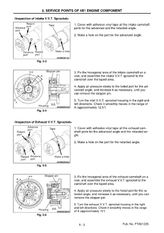
           < << <Inspection of Intake V.V.T. Sprocket>

                                                       1. Cover with adhesive vinyl tape all the intake camshaft
                                                       ports for the advanced and the retarded angle.

                                                       2. Make a hole on the port for the advanced angle.


                            Fig. 5-3


                                                       3. Fix the hexagonal area of the intake camshaft on a
                                                       vise, and assemble the intake V.V.T. sprocket to the
                                                       camshaft over the taped area.

                                                       4. Apply air pressure slowly to the holed port for the ad-
                                                       vanced angle, and increase it as necessary, until you
                                                       can remove the stopper pin.

                                                       5. Turn the inlet V.V.T. sprocket housing in the right and
                                                       left directions. Check it smoothly moves in the range of
                                                       A (approximately 12.5°)
                            Fig. 5-4


           < << <Inspection of Exhaust V.V.T. Sprocket>
                                                       1. Cover with adhesive vinyl tape all the exhaust cam-
                                                       shaft ports for the advanced angle and the retarded an-
                                                       gle.

                                                       2. Make a hole on the port for the retarded angle.


                            Fig. 5-5


                                                       3. Fix the hexagonal area of the exhaust camshaft on a
                                                       vise, and assemble the exhaust V.V.T. sprocket to the
                                                       camshaft over the taped area.

                                                       4. Apply air pressure slowly to the holed port for the re-
                                                       tarded angle, and increase it as necessary, until you can
                                                       remove the stopper pin.

                                                       5. Turn the exhaust V.V.T. sprocket housing in the right
                                                       and left directions. Check it smoothly moves in the range
                                                       of A (approximately 10°)
                            Fig. 5-6


                                                          5 - 2                           Pub. No. PTAE1225
   24   25   26   27   28   29   30   31   32   33   34