
Page 30 - E BOOK ENGINE MECHANICAL M2
P. 30
5. SERVICE POINTS OF 4B1 ENGINE COMPONENT
<Valve Clearance Check and Adjustment>
Note Perform the valve clearance check and adjustment when engine is cold.
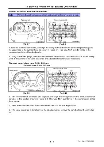
Fig. 5-7 Fig. 5-8
1. Turn the crankshaft clockwise, and align the timing mark on the intake camshaft sprocket against
the upper face of the cylinder head as shown in Figure 5-7. This way, No.1 cylinder will be in the
compression stroke at top dead center.
2. Using a thickness gauge, measure the valve clearance of the valves shown with the arrows in Fig-
ure 5-8. Make note of the valve clearance and adjust to standard value if necessary.
Standard value: Intake valve 0.20 ± 0.03 mm
Exhaust valve 0.30 ± 0.03 mm
Fig. 5-9 Fig. 5-10
3. Turn the crankshaft clockwise 360 degrees, and align the timing mark on the exhaust camshaft
sprocket in the position shown in Figure 5-9. This way, No.4 cylinder is in the compression at top
dead center.
4. Check the valve clearance of the valves shown with the arrow in Figure 5-10.
5. If the valve clearance is deviated from the standard value, remove the camshaft and the valve tap-
pet.
5 - 3 Pub. No. PTAE1225