Page 32 - E BOOK ENGINE MECHANICAL M2
P. 32

5. SERVICE POINTS OF 4B1 ENGINE COMPONENT


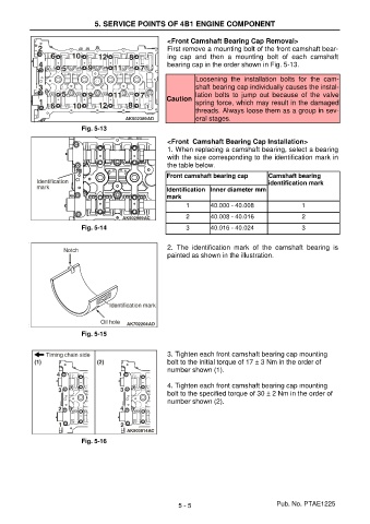
                                                       <Front Camshaft Bearing Cap Removal>
                                                       First remove a mounting bolt of the front camshaft bear-
                                                       ing  cap  and  then  a  mounting  bolt  of  each  camshaft
                                                       bearing cap in the order shown in Fig. 5-13.

                                                                Loosening  the  installation  bolts  for  the  cam-
                                                                shaft bearing cap individually causes the instal-
                                                                lation  bolts  to  jump  out  because  of  the  valve
                                                       Caution
                                                                spring force, which may result in the damaged
                                                                threads. Always loose them as a group in sev-
                                                                eral stages.
                           Fig. 5-13

                                                       <Front  Camshaft Bearing Cap Installation>
                                                       1. When replacing a camshaft bearing, select a bearing
                                                       with the size corresponding to the identification mark in
                                                       the table below.
                                                       Front camshaft bearing cap      Camshaft bearing
                                                                                       identification mark
                                                       Identification  Inner diameter mm
                                                       mark
                                                             1       40.000 - 40.008              1
                                                             2       40.008 - 40.016              2
                           Fig. 5-14                         3       40.016 - 40.024              3


                                                       2.  The  identification  mark  of  the  camshaft  bearing  is
                                                       painted as shown in the illustration.


                           Fig. 5-15


                                                       3. Tighten each front camshaft bearing cap mounting
                                                       bolt to the initial torque of 17 ± 3 Nm in the order of
                                                       number shown (1).

                                                       4. Tighten each front camshaft bearing cap mounting
                                                       bolt to the specified torque of 30 ± 2 Nm in the order of
                                                       number shown (2).


                           Fig. 5-16


                                                          5 - 5                           Pub. No. PTAE1225
   27   28   29   30   31   32   33   34   35   36   37