
Page 33 - E BOOK ENGINE MECHANICAL M2
P. 33
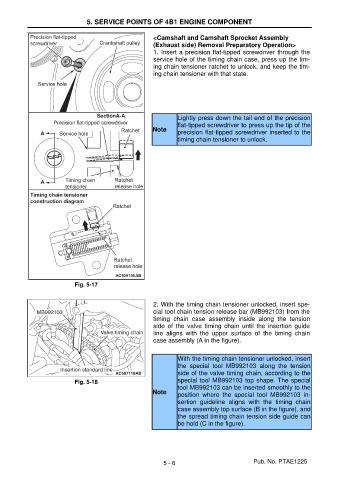
5. SERVICE POINTS OF 4B1 ENGINE COMPONENT


                                                       <Camshaft and Camshaft Sprocket Assembly
                                                       (Exhaust side) Removal Preparatory Operation>
                                                       1. Insert a precision flat-tipped screwdriver through the
                                                       service hole of the timing chain case, press up the tim-
                                                       ing chain tensioner ratchet to unlock, and keep the tim-
                                                       ing chain tensioner with that state.


                                                               Lightly press down the tail end of the precision
                                                               flat-tipped screwdriver to press up the tip of the
                                                       Note
                                                               precision flat-tipped screwdriver inserted to the
                                                               timing chain tensioner to unlock.


                           Fig. 5-17


                                                       2. With the timing chain tensioner unlocked, insert spe-
                                                       cial tool chain tension release bar (MB992103) from the
                                                       timing  chain  case  assembly  inside  along  the  tension
                                                       side  of  the  valve  timing  chain  until  the  insertion  guide
                                                       line  aligns  with  the  upper  surface  of  the  timing  chain
                                                       case assembly (A in the figure).


                                                               With the timing chain tensioner unlocked, insert
                                                               the  special  tool  MB992103  along  the  tension
                                                               side of the valve timing chain, according to the
                           Fig. 5-18                           special tool MB992103 top shape. The special
                                                               tool MB992103 can be inserted smoothly to the
                                                       Note
                                                               position  where  the  special  tool  MB992103  in-
                                                               sertion  guideline  aligns  with  the  timing  chain
                                                               case assembly top surface (B in the figure), and
                                                               the spread timing chain tension side guide can
                                                               be hold (C in the figure).


                                                          5 - 6                           Pub. No. PTAE1225